Heating systems for hydrogen storage materials

A technology for storage materials and heaters, which is applied in the field of hydrogen storage and delivery systems, and can solve problems such as the efficiency limitation of electric heaters

Inactive Publication Date: 2010-10-06
GM GLOBAL TECH OPERATIONS LLC
View PDF0 Cites 6 Cited by
  • Summary
  • Abstract
  • Description
  • Claims
  • Application Information

AI Technical Summary

Problems solved by technology

But the problem with this approach is that the efficiency of the electric he...

Method used


Image

  • Heating systems for hydrogen storage materials
  • Heating systems for hydrogen storage materials
  • Heating systems for hydrogen storage materials

Examples


example 1

Example 1 - Catalytic Heater (Indirect Heating)

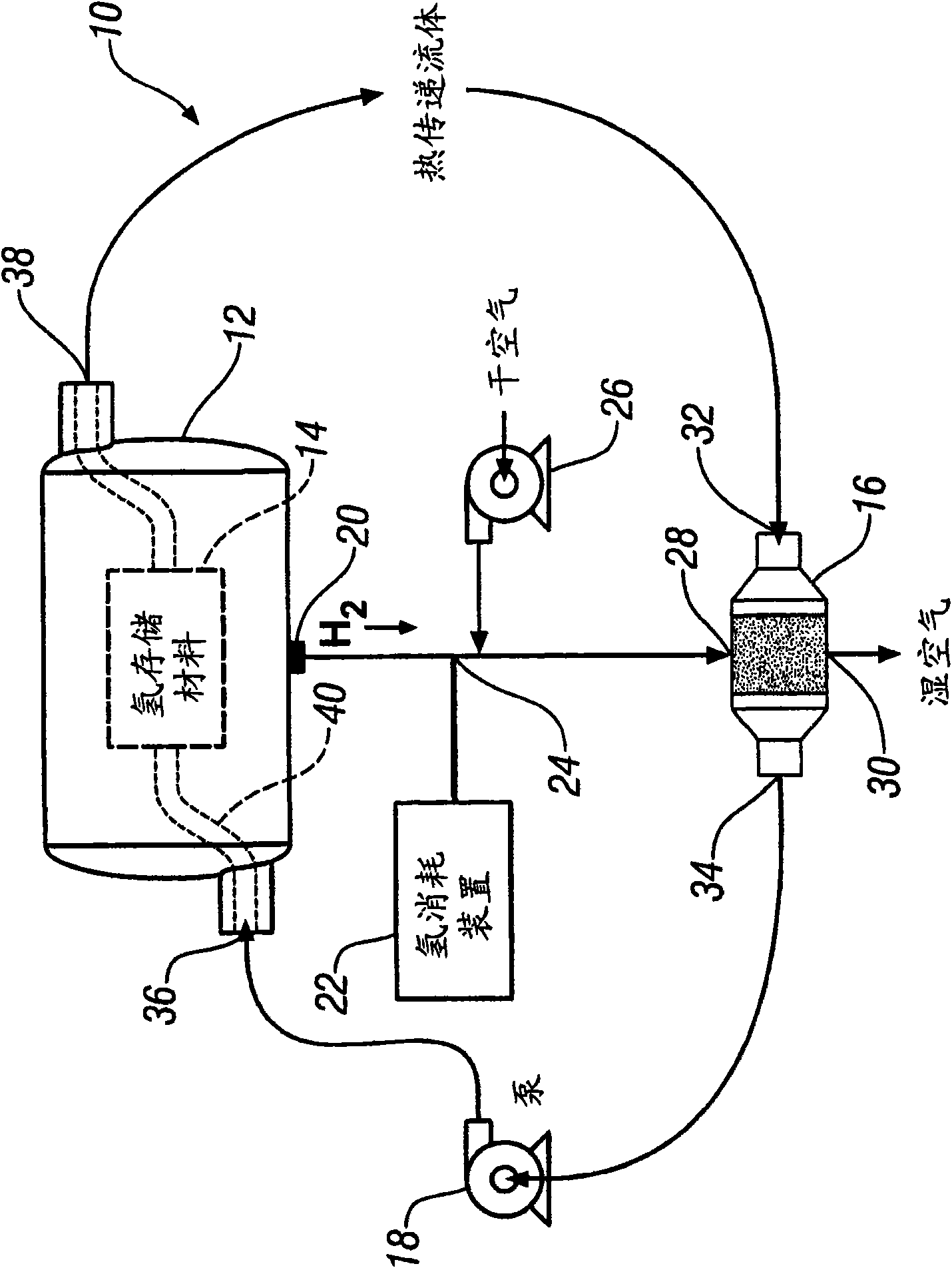
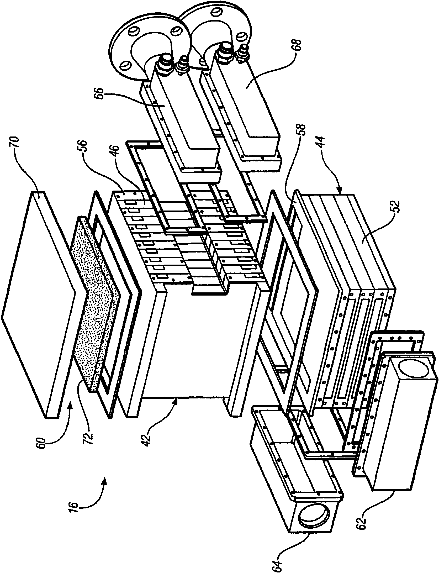
[0063] Specific embodiments of the catalytic heater 16' have been provided, used herein with Figure 1-3 Corresponding primary numerals in like reference numerals denote that it is capable of transferring more than 30 KW of heat from the catalytic combustion of hydrogen and oxygen to the heat transfer fluid. The size, shape and configuration of the reactor 42' and gas heat exchanger 44' have been adjusted and optimized in an attempt to maximize heat transfer to the heat transfer fluid while minimizing the mass and volume of the catalytic heater 16'.

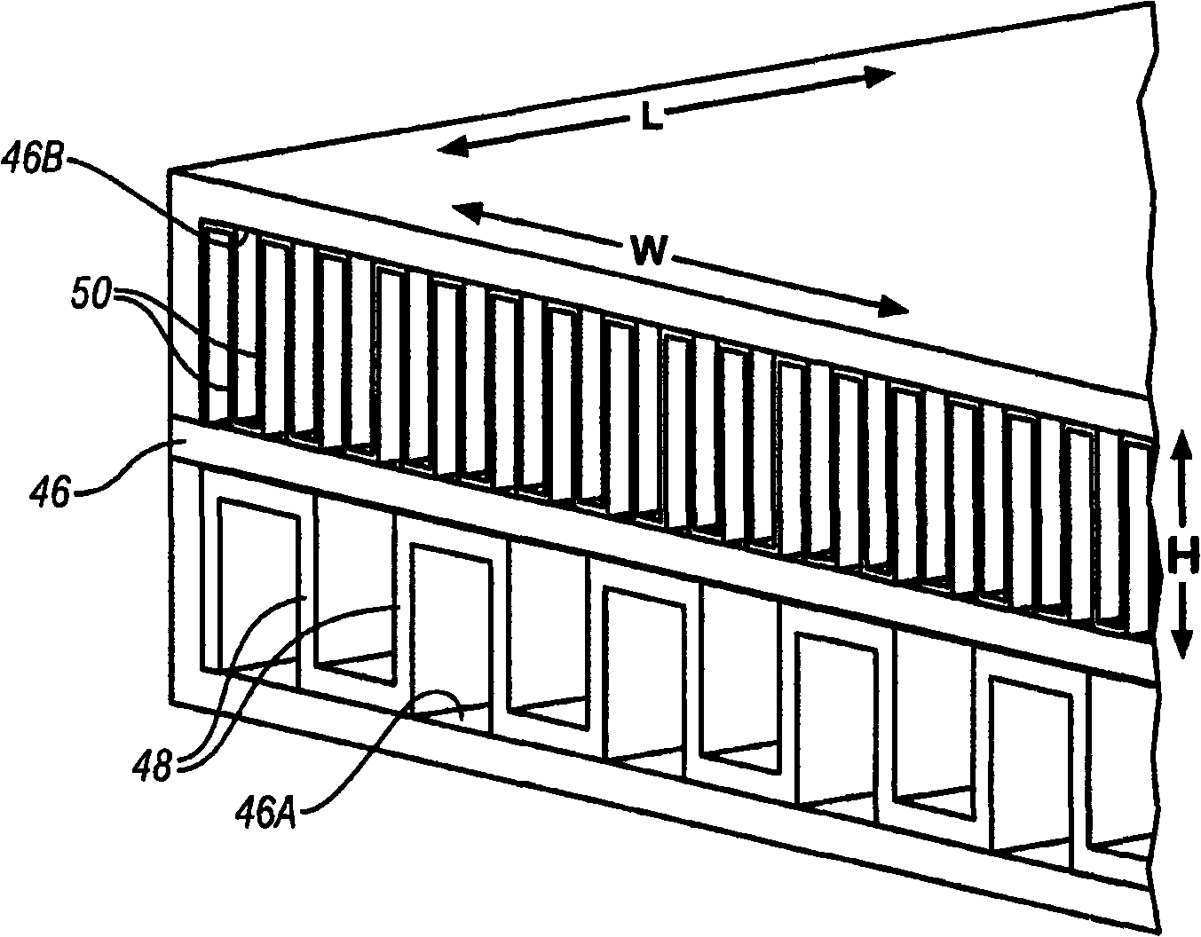
[0064] In this embodiment, the reactor 42' comprises a Figure 2-3 Ten heat transfer layers 46' are shown and similar to those described. Ten layers 46' are brazed together to form alternating and parallel gas flow channels 46A' and liquid flow channels 46B' which allow co-current flow. Each of the layers 46' has a length L (along which the reactant gas mixture and heat transfer...


PUM


Abstract

Auxiliary heating systems that can supply heat to a hydrogen storage material, which may comprise at least one hydridable material, located inside a hydrogen storage tank have been developed. These auxiliary heating systems involve the catalytic combustion of hydrogen and oxygen in a catalytic heater to produce heat and combustion products. The heat produced from the catalytic combustion may then be transferred, either indirectly or directly, to the hydrogen storage material to stimulate the release of additional desorbable hydrogen that may be stored in the at least one hydrdidable material.

Description

[0001] Cross References to Related Applications [0001] This application claims the benefit of US Provisional Application No. 61 / 096,019, filed September 11, 2008. technical field [0002] The technical field relates generally to hydrogen storage and delivery systems for hydrogen consuming devices. Background technique [0003] The use of hydrogen as a possible fuel source for hydrogen consuming devices, such as vehicles, has stimulated research into hydrogen storage and delivery technologies. One particular area of ​​focus includes the desire to store effective quantities of hydrogen in storage tanks that operate within relatively moderate temperature and pressure ranges. To test and complete this art, considerable attention has been directed to hydrogen storage materials, including hydrogen absorbing materials capable of reversibly forming hydrides in the presence of hydrogen gas. There are many hydrogen-absorbing materials that are capable of reversibly adsorbing and ...

Claims


Application Information

Patent Timeline
IPC IPC(8): F17C11/00
CPCH01M8/04216Y02E60/321C01B3/001C01B3/0031H01M8/04208F23C13/00Y02E60/50Y02E60/327F23C2900/9901C01B3/0026Y02E60/32
Inventor T·A·约翰逊D·E·德德里克M·P·卡诺夫
Owner GM GLOBAL TECH OPERATIONS LLC
Why Eureka
Try Eureka