Device for measuring and adjusting weight, center of gravity and rotary inertia of ship model

A moment of inertia and adjusting device technology, applied in the field of measuring instruments, can solve the problems of high center of gravity, small rotation angle, and reduced measurement accuracy of the rotating system, and achieve the effects of high measurement and adjustment accuracy, increased restoring torque, and improved stability

Inactive Publication Date: 2010-10-06
HARBIN ENG UNIV
View PDF4 Cites 26 Cited by
  • Summary
  • Abstract
  • Description
  • Claims
  • Application Information

AI Technical Summary

Problems solved by technology

[0005] Through literature search, it is found that the Chinese patent publication number is CN 1544888A, and the patent name is: digital ship model inertia adjustment frame. The device invented by this patent improves the accuracy and efficiency of the measurement and adjustment of the weight, center of gravity and moment of inertia of the ship model to a certain extent. , but there are the following disadvantages: (1) The center of gravity of the inertia frame and the ship model is above the rotating knife edge, and the center of gravity of the rotating system composed of the inertia frame and the ship model is high, and it is difficult to maintain stability when rotating and loading, which reduces the accuracy of measurement and adjustment and efficiency; (2) The vertical position of the center of gravity and the moment of inertia are measured using the principle of a micro-complex pendulum. The rotation angle of the system is small, and the rotation angle of the rotation system is not enlarged, which brings a large angle measurement error and reduces the measurement accuracy; (3) Its structure is inconvenient to measure the moment of inertia of ship model roll

Method used


Image

  • Device for measuring and adjusting weight, center of gravity and rotary inertia of ship model
  • Device for measuring and adjusting weight, center of gravity and rotary inertia of ship model
  • Device for measuring and adjusting weight, center of gravity and rotary inertia of ship model

Examples


Embodiment Construction

[0017] The present invention is described in more detail below in conjunction with accompanying drawing example:

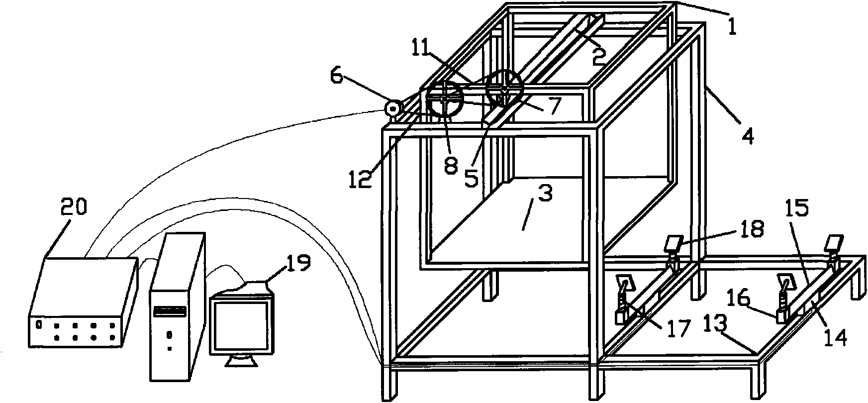
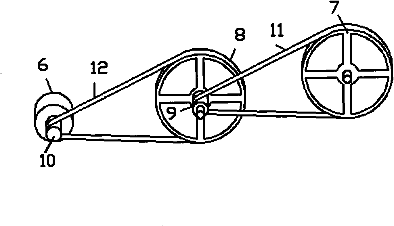
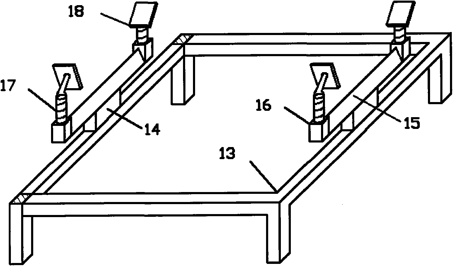
[0018] to combine Figure 1~4 , The invention patent includes inner rotating part, outer supporting part, angle magnification and measuring system, weighing part, data acquisition and analysis processing system. The inner rotating part includes a rotating frame 1 , a rotating knife edge 2 and a base plate 3 . The rotating knife edge 2 is fixedly connected under the top frame of the turret 1 , and the base plate 3 is fixedly connected above the bottom frame of the turret 1 ; the outer support part includes an outer support frame 4 and a knife groove 5 . The sieve 5 is fixedly connected to the middle position above the top frame of the outer support frame 4; the angle magnification and measurement system includes an angle sensor 6, a driving wheel 7, a driven main wheel 8, a driven auxiliary wheel 9, a sensor shaft wheel 10, and a primary transmission belt 11 and ...


PUM


Abstract

The invention aims at providing a device for measuring and adjusting weight, center of gravity and rotary inertia of a ship model, which comprises a frame, a knife edge, a knife groove, a substrate, a wheel, a sensor and a base. The invention has high measuring and adjusting accuracy, reduces the error caused by angular surveying through an angle amplifying module and further improves the measuring and adjusting accuracy of the device. The invention has good stability, and the center of gravity of the system formed by the inner rotary part and the ship mode is located below the rotary knife edge, thereby increasing the restoring torque and improving the stability of the rotary system. The inner rotary part and the outer support part are designed in a form that ensures that the measurement and adjustment of weight, center of gravity and rotary inertia of the ship model including rolling rotary inertia can be realized conveniently. The invention integrates measurement and adjustment, i.e. the device measures weight, the center of gravity and rotary inertia of the ship model into a whole.

Description

technical field [0001] The invention relates to a measuring instrument, in particular to a device for measuring and adjusting the physical quantity of a mechanical structure. Background technique [0002] The ship model tank test is used to simulate the real sailing state of a real ship. In order to make the test data closer to the real state, the gravity and inertia of the ship model and the real ship must be kept similar. In the test preparation, the parameters of the model must be adjusted according to the needs and given values: the weight, center of gravity and moment of inertia of the ship model. The weight of the ship model is the basis for measuring other parameters of the ship model. The measurement and calculation process of many performance parameters of the ship model are based on the weight of the ship model. Therefore, the measurement of the weight of the ship model must be carried out as accurately as possible, especially In the ship resistance test, the acc...

Claims


Application Information

Patent Timeline
Patent Type & Authority Applications(China)
IPC IPC(8): G01G19/00G01M1/12G01M1/10B63B9/00
Inventor 马勇张亮郭春雨周广利由世洲李凤来
Owner HARBIN ENG UNIV
Why Eureka
Try Eureka