Method and device for multifocal holographic differential confocal super-long focus measurement

A differential confocal and measurement device technology, applied in the direction of testing optical performance, etc., to achieve the effect of reducing influence, improving measurement accuracy and reducing influence

Inactive Publication Date: 2011-11-09
BEIJING INSTITUTE OF TECHNOLOGYGY
View PDF1 Cites 2 Cited by
  • Summary
  • Abstract
  • Description
  • Claims
  • Application Information

AI Technical Summary

Problems solved by technology

[0009] The purpose of the present invention is to solve the problem of high-precision measurement of small numerical aperture and ultra-long focal length lenses, and propose a method that uses the focal point of the ultra-long focal length lens to be measured and the first-order focus of the multi-focal holographic lens when the differential confocal response curve crosses zero. The coincidence feature realizes the measurement of the focal length of the ultra-long focal length lens

Method used


Image

  • Method and device for multifocal holographic differential confocal super-long focus measurement
  • Method and device for multifocal holographic differential confocal super-long focus measurement
  • Method and device for multifocal holographic differential confocal super-long focus measurement

Examples


Embodiment 1

[0047] When the measured super long focal length lens 4 is a convex lens with a focal length of 10m, as Figure 7 As shown, the differential confocal ultra-long focal length measurement device, the measurement steps are:

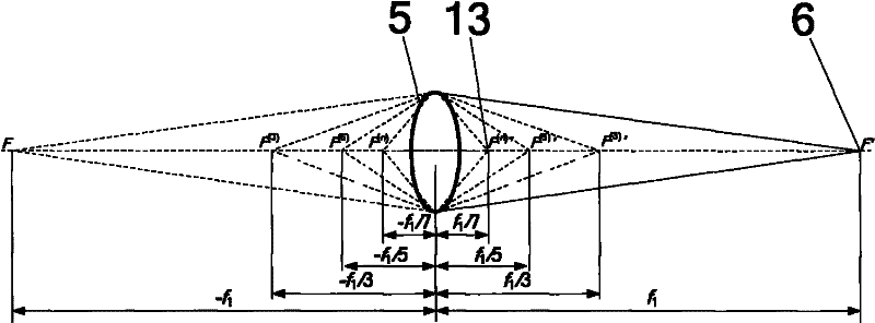
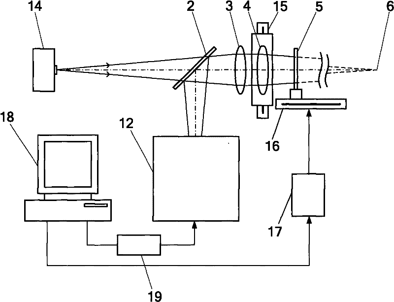
[0048] First, use the standard lens 28 with a focal length of 1200mm to calibrate the first-order focal length of the multi-focal holographic lens 5, as figure 2 As shown, it is known that the first-order focal length of the multifocal holographic lens 5 is f′ 1 , in addition to multiple higher-order foci, respectively at ±f′ 1 / 3, ±f' 1 / 5, ±f' 1 / 7, ±f' 1 / 9 and other positions, the focal length values ​​corresponding to each focal point have a linear relationship. like Figure 8 As shown, the calibration steps are as follows:

[0049] (a) Start the measurement software in the main control computer 18, turn on the laser light source 24, and the laser light emitted by the laser light source 24 is transmitted through the optical fiber 23 to form a po...

Embodiment 2

[0063] When the measured ultra-long focal length lens 4 is a concave lens with a focal length of 10 m, the difference from Embodiment 1 is that the first-order focal length of the selected multi-focal holographic lens should be greater than 10 m. The calibration steps of the multi-focus holographic lens are the same as those in Embodiment 1. In the measurement step (c), the multifocal holographic lens is scanned along the optical axis, and the apex of the differential confocal light cone coincides with the negative first-order focus of the multifocal holographic lens by detecting the absolute zero point of the differential confocal response curve. The rest of the measurement steps are the same as in Example 1.

Embodiment 3

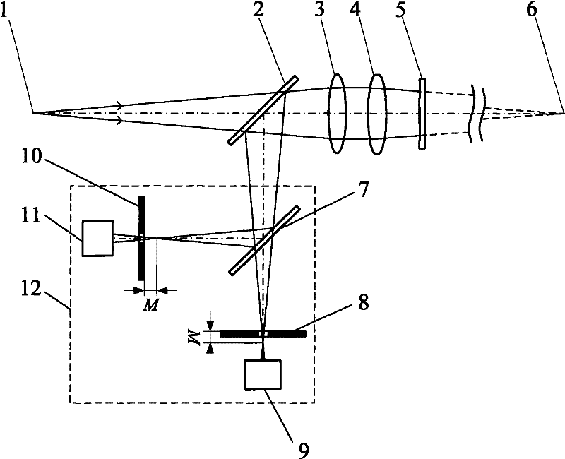
[0065] Different from Embodiment 1 or Embodiment 2, the differential confocal system 12 using pinhole detection can also be replaced by Figure 4 The shown direct detection differential confocal system includes the second beam splitter 7, the first light intensity sensor 9 and the second light intensity sensor 11; the light reflected by the first beam splitter 2 enters the differential confocal The focus system 12 divides the light into two paths by the second beam splitter 7, and one path is irradiated on the first light intensity sensor 9 located in front of the focus, and the other path is irradiated on the second light intensity sensor 11 positioned behind the focus; wherein the first The light intensity sensor 9 can be embodied as a CCD detector 25 , and the second light intensity sensor 11 can be embodied as a CCD detector 26 , and the subsequent measurement process is as described in Embodiment 1 or Embodiment 2.


PUM


Abstract

The invention belongs to the technical field of optical precise measurement and relates to a method and a device for multifocal holographic differential confocal super-long focus measurement. In the method, a differential confocal system is used for calibrating the long focus value of a multifocal holographic lens so as to reduce system errors for measurement; and then, the focus of a super long focus lens is measured according to the characteristic that the focal point of the measured super long focus lens coincides with the first-order focal point of the multifocal holographic lens when a differential confocal response curve passes through the zero point. The device comprises a point light source, a first spectroscope, a collimating lens, a multifocal holographic lens and a differentialconfocal system, wherein the first spectroscope, the collimating lens and the multifocal holographic lens are sequentially arranged in the exit direction of light, the differential confocal system isarranged in the reflection direction of the first spectroscope, and the multifocal holographic lens and the first spectroscope reflect a light beam to the differential confocal system and cooperates with the differential confocal system to realize the precise positioning of the differential confocal light cone vertex exiting from the measured super long focus lens. The invention has the advantages of small displacement distance of the measured part, high measurement precision, high measurement speed, high environmental intrusion resistance and the like, and can be used for the high precision measurement of the super long focus.

Description

technical field [0001] The invention belongs to the technical field of optical precision measurement and can be used for the detection of ultra-long focal length lenses and the high-precision ultra-long focal length measurement in the assembly process of optical systems. technical background [0002] In recent years, ultra-long focal length lenses have been widely used in large-scale optical systems such as high-energy lasers and astronomical telescopes. The processing, testing and assembly of such large-scale lenses are very difficult. As an important parameter of an ultra-long focal length lens, its focal length measurement has always been a difficult point in the field of optical measurement. The main factors are: small numerical aperture and long depth of focus make it difficult to achieve precise focusing; Susceptible to environmental disturbances. Due to the above reasons, traditional fixed-focus methods such as the magnification method or the pentaprism method are di...

Claims


Application Information

Patent Timeline
Patent Type & Authority Patents(China)
IPC IPC(8): G01M11/02
Inventor 赵维谦杨佳苗孙若端邱丽荣
Owner BEIJING INSTITUTE OF TECHNOLOGYGY
Why Eureka
Try Eureka