
Video image denoising device and method

A video image and noise reduction technology, which is applied in the field of video image processing devices, can solve problems such as image transition unevenness, blocking, etc., and achieve the effect of noise removal and noise elimination

Active Publication Date: 2014-03-12
ARKMICRO TECH
View PDF3 Cites 0 Cited by
  • Summary
  • Abstract
  • Description
  • Claims
  • Application Information

AI Technical Summary

Problems solved by technology

This method can properly balance the denoising performance and image blur. However, since the neighborhood operation points selected by each point in the image are different, the image transition will often be uneven, especially when the image changes from a flat area to an image. In abrupt areas, such as the outline of a human face or the junction of blue sky and white clouds, this noise reduction method will cause obvious transition unevenness and block phenomenon in the image

Method used


Image

  • Video image denoising device and method
  • Video image denoising device and method
  • Video image denoising device and method

Examples


Embodiment Construction

[0060] The specific embodiment of the present invention will be described in detail below in conjunction with the accompanying drawings.

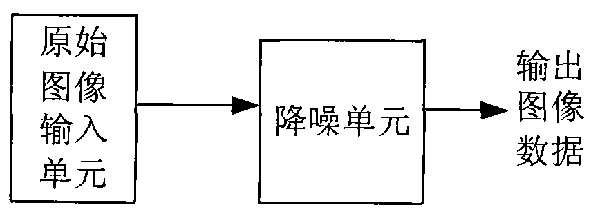
[0061] Such as figure 1 Shown is a structural block diagram of a traditional noise reduction device. The structure includes an original image input unit and a noise reduction unit. The original image input unit outputs original image data to the noise reduction unit, and the image data is output after being denoised by the noise reduction unit. The traditional noise reduction device outputs after noise reduction processing, and when the noise reduction effect is outstanding, the image will be blurred.

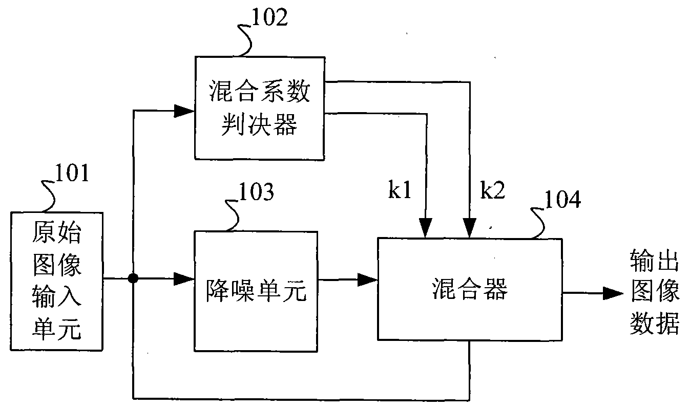
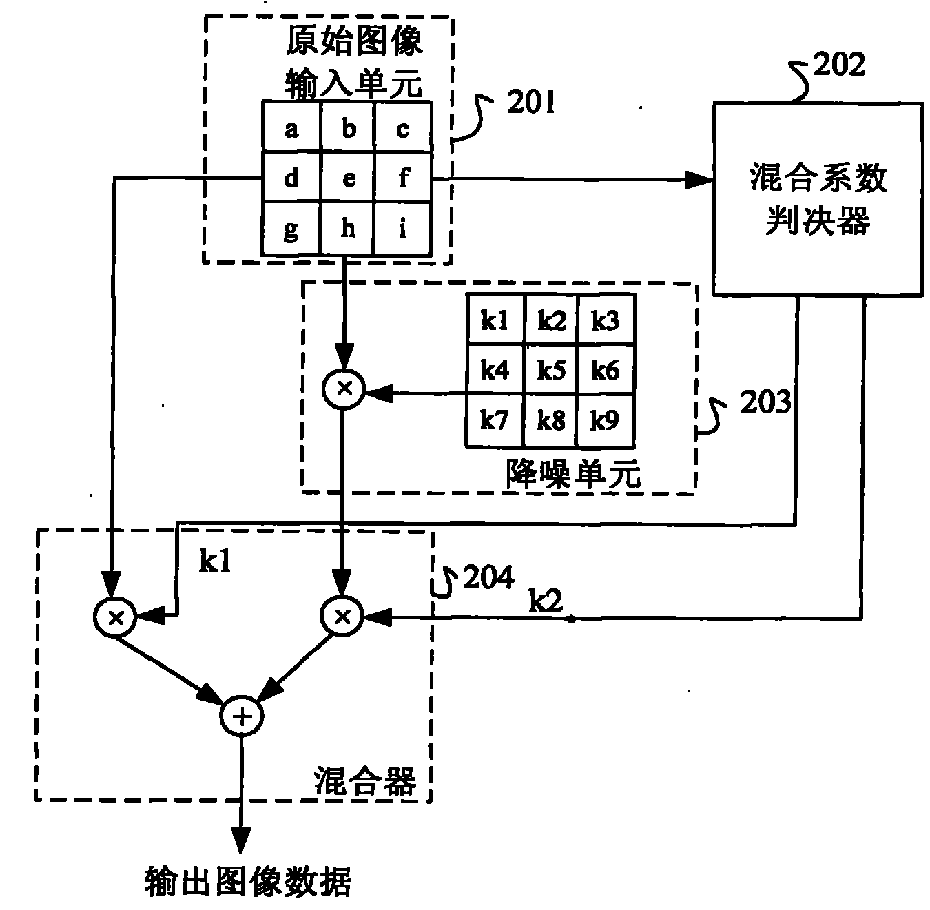
[0062] Such as figure 2 Shown is a structural block diagram of a video image noise reduction device according to a specific embodiment of the present invention. The structure includes an original image input unit 101, a mixing coefficient determiner 102, a noise reduction unit 103, and a mixer 104. The original image input unit 101 convert...


PUM


Abstract

The invention discloses a video image denoising device. The device comprises an original image inputting unit, a denoising unit, a mixing coefficient judging device and a mixer, wherein the original image inputting unit inputs original image data to the denoising unit and simultaneously to the mixing coefficient judging device and the mixer; and the denoised image data output by the denoising unit, the mixing coefficient output by the mixing coefficient judging device and the original image data are mixed in the mixer to acquire output image data. The invention also discloses a video image denoising method. The device and the method have the advantages of removing noise in an image, keeping original details of the image, and simultaneously avoiding the transition problem of uniform images.

Description

technical field [0001] The present invention relates to a video image processing device and method, in particular to a device and method for noise reduction processing of video images. Background technique [0002] Image noise reduction technology is widely used in video image processing. The purpose of image noise reduction is to restore the original image without distortion as much as possible and eliminate noise. [0003] The more common noise signals are Gaussian noise and impulse noise. Impulse noise is isolated noise mixed into the image, and the correlation between the noise point and the surrounding points is very poor. Generally, the median filter can be used to filter out this noise. Gaussian noise is uniform white noise mixed into the image, which has nothing to do with the image itself. The method of filtering the noise generally adopts one-dimensional or two-dimensional average filtering, one-dimensional or two-dimensional Gaussian filtering, or one-dimensional...

Claims


Application Information

Patent Timeline
Patent Type & Authority Patents(China)
IPC IPC(8): G06T5/00
Inventor 李琛刘俊秀周显文石岭王雅君
Owner ARKMICRO TECH
Learn More