
Wireless transmission video monitoring system and method

A video surveillance system and wireless transmission technology, applied in the field of video, can solve the problems of insufficient wireless channels, high real-time requirements, limited wireless channel resources, etc., and achieve the effect of breaking through geographical restrictions, satisfying real-time performance, and smooth real-time images

Inactive Publication Date: 2010-10-06
广东中大讯通信息有限公司 +2
View PDF5 Cites 13 Cited by
  • Summary
  • Abstract
  • Description
  • Claims
  • Application Information

AI Technical Summary

Problems solved by technology

[0006] (2) High real-time requirements
[0008] Due to the limited wireless channel resources in the wireless network environment, if it is necessary to realize the transmission of video signals with a large amount of data, especially in wireless visual applications for the public, the wireless channel resources may be insufficient. In addition, in mobile communications, users The mobile QoS guarantee of wireless video is very complicated
[0009] Therefore, it can be found that in the prior art, there is a sharp contradiction between the need for video signal transmission and the characteristics of the wireless environment, and the existing wireless transmission video monitoring method needs to be improved.

Method used


Image

  • Wireless transmission video monitoring system and method
  • Wireless transmission video monitoring system and method
  • Wireless transmission video monitoring system and method

Examples


Embodiment Construction

[0054] In order to enable those skilled in the art to better understand the solution of the present invention, the present invention will be further described in detail below with reference to the accompanying drawings and embodiments:

[0055] The system of the present invention can be applied to a narrowband wireless network environment and can be run on a digital home interactive application service platform.

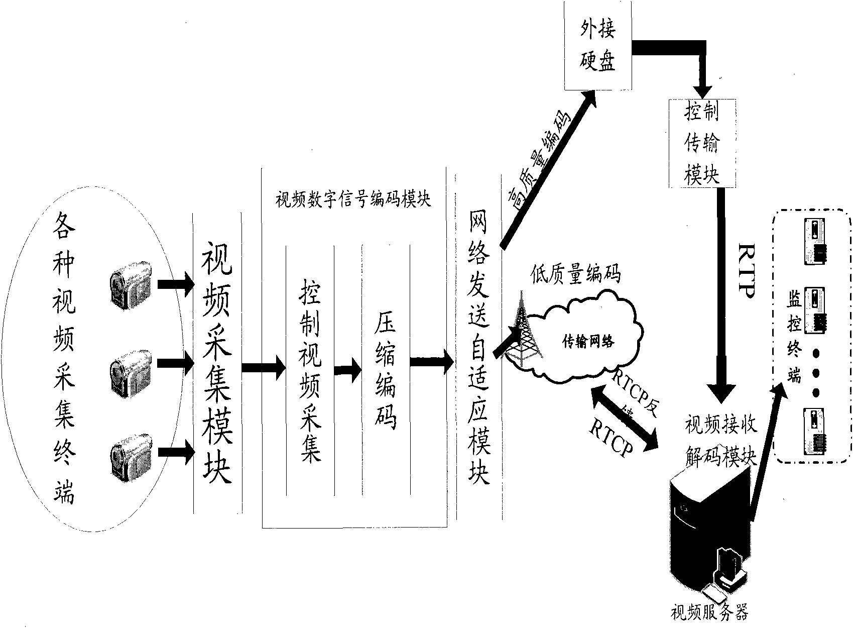
[0056] figure 1 It is a system structure diagram of an embodiment of the invention. Such as figure 1 As shown, the system includes:

[0057] Various video acquisition terminals, video acquisition modules, video digital signal encoding modules, network transmission adaptive modules, control transmission modules, video receiving and decoding modules, monitoring terminals, etc.

[0058] among them,

[0059] The video collection module is used to collect video data through a video collection terminal;

[0060] The video digital signal encoding module is configured to acquire the v...


PUM


Abstract

The invention discloses a wireless transmission video monitoring system and a wireless transmission video monitoring method. The system comprises a video acquisition module, a video digital signal coding module, a network sending adaptive module, a control transmission module, a video receiving decoding module and a monitoring terminal, wherein the video acquisition module is used for acquiring video data through a video acquisition terminal; the video digital signal coding module is used for acquiring the video data acquired by the video acquisition module and compressing and coding the video data by using an image group bit distribution method and a foreground-background decomposing and coding method; the network sending adaptive module is used for adaptively selecting a network environment aiming at different network environments of gateway routing equipment to perform communication; the control transmission module is used for managing network state reports generated by each independent network monitoring; the video receiving decoding module is used for receiving real-time video data from a network, identifying the source of each path of video data in multi-path transmission and analyzing and decoding the received video data; and the monitoring terminal is used for acquiring the decoded real-time video data and playing the decoded real-time video data through a player. The scheme of the invention can perform good wireless transmission under a narrowband network environment.

Description

Technical field [0001] The present invention relates to the field of video technology, in particular to a wireless transmission video monitoring system and method in a narrowband wireless network environment. Background technique [0002] With the rapid development of science and technology, home safety of various science and technology products is related to the safety of people's family and property. It has always been a major concern of people. Video surveillance systems have become a necessary device for home safety considerations. [0003] The digital video signal has the following characteristics: [0004] (1) Large amount of data [0005] Mobile video phones generally use QCIF (quarter common immediate format, quarter common immediate format) resolution images, which have 176X144=25344 pixels. If each pixel is represented by 24 bits, the data volume of one frame of image still reaches 594kbit. Taking into account the frame rate required for real-time video image transmission ...

Claims


Application Information

Patent Timeline
IPC IPC(8): H04N7/18H04N7/26
Inventor 罗笑南刘宁曹旦森王炅
Owner 广东中大讯通信息有限公司
Learn More