Droplet break-up device

A technology of breaking device and droplet, applied in the direction of inking device, printing, etc., can solve the problem of difficult to achieve high frequency

Inactive Publication Date: 2010-10-06
NEDERLANDSE ORG VOOR TOEGEPAST NATUURWETENSCHAPPELIJK ONDERZOEK TNO
View PDF1 Cites 5 Cited by
  • Summary
  • Abstract
  • Description
  • Claims
  • Application Information

AI Technical Summary

Problems solved by technology

However, higher frequencies are difficult to achieve due to the size of the chassis

Method used


Image

  • Droplet break-up device
  • Droplet break-up device
  • Droplet break-up device

Examples


Embodiment Construction

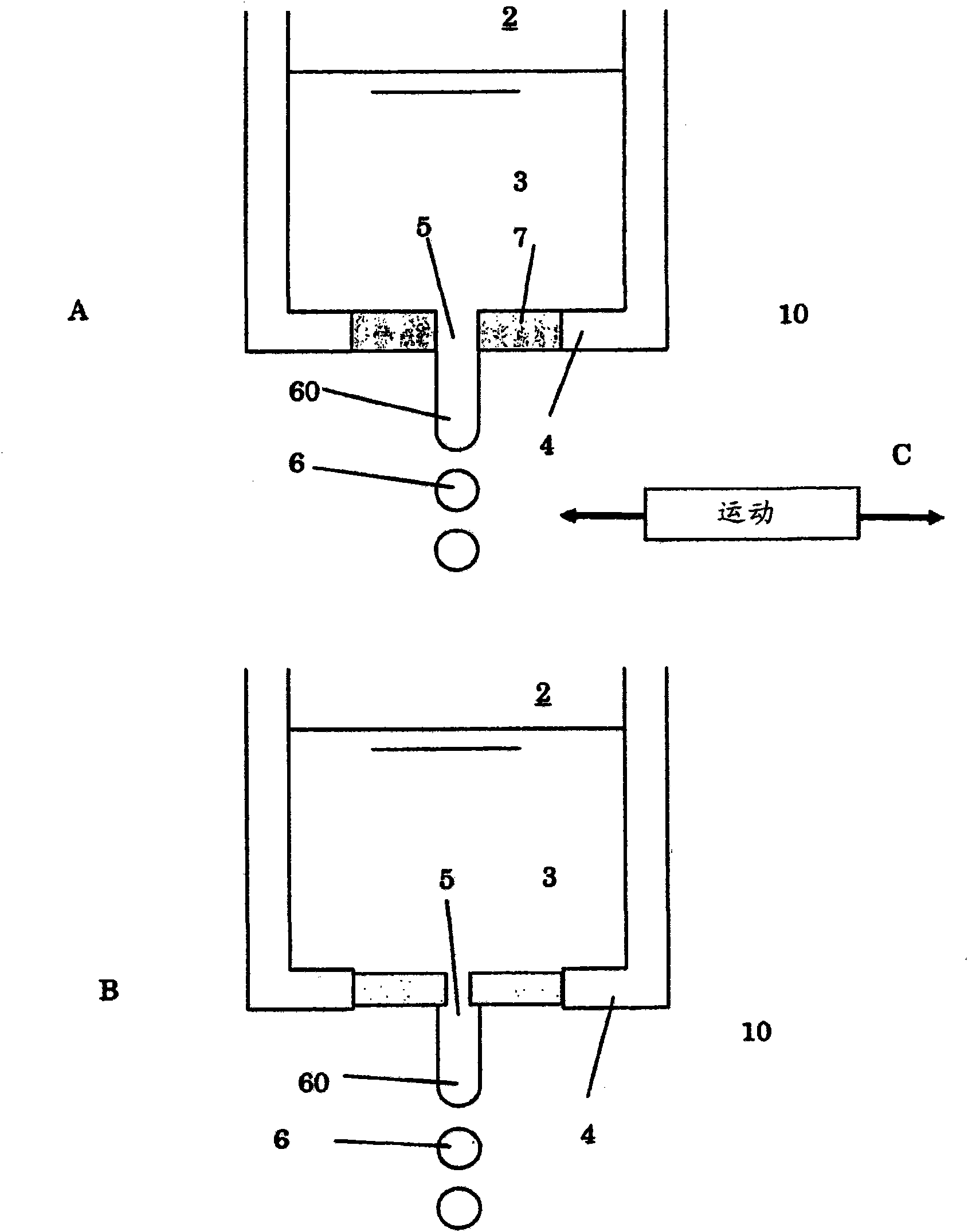
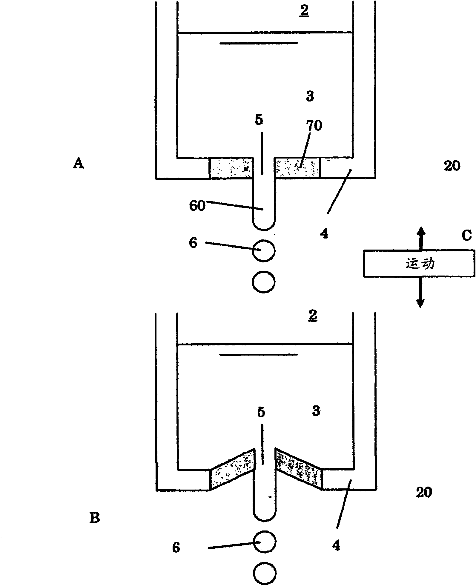
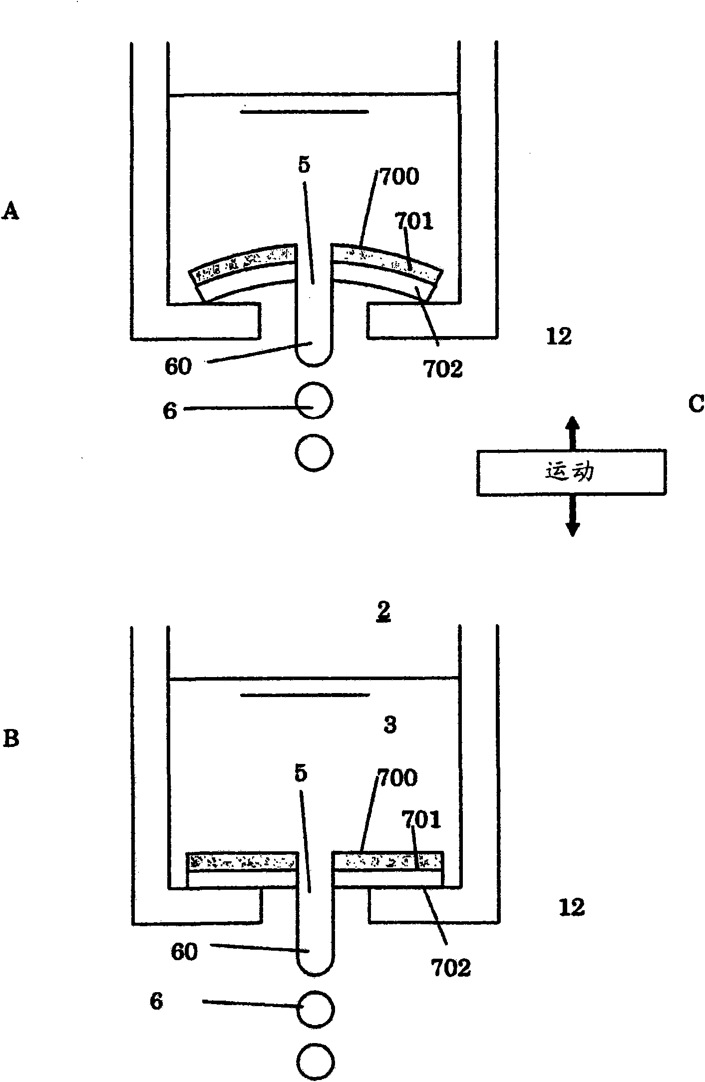
[0017] In the following, parts A, B and C represent the corresponding operating positions and actuating directions of the actuators.

[0018] figure 1 A first schematic embodiment of a droplet breaking device according to the invention is shown. In particular, drop break-off device (also referred to as printhead) 10 comprises a chamber 2 comprising a base plate 4 . The chamber 2 is adapted to contain a liquid 3 under pressure, for example by a pump or by a pressurized supply (not shown). The chamber 2 comprises an outlet duct 5 through which a pressurized fluid jet 60 is broken into droplets 6 . The outlet tube defines a central axis and around the outlet tube an actuator 7 is formed and substantially symmetrical with respect to the central axis of the outlet tube 5 . The actuator is preferably a piezoelectric element or a magnetostrictive element in the form of an annular disk arranged in the bottom plate 4 . By actuation of the actuator 7 a pressure pulse is formed which...


PUM


Abstract

The invention relates to a droplet break up device comprising: a chamber (2) for containing a printing liquid (3) comprising a bottom plate (4); a pump for pressurizing the printing liquid; an outlet channel (5) having a central axis, provided in said chamber for ejecting the printing liquid; and an actuator (7) for breaking up a fluid jetted out of the -outlet channel. The actuator is provided around the outlet channel, arranged to symmetrically impart a pressure pulse central to the outlet channel axis. Accordingly, smaller droplets can be delivered at higher frequencies.

Description

technical field [0001] The present invention relates to a droplet break-up device, in the field known as drop-on-demand systems or continuous printing systems, which is configured in various ways from a printing nozzle Spray droplets. In this regard, the term "printing" generally refers to the formation of small droplets, and is especially not limited to the formation of images. Background technique [0002] In this regard, by continuous jet printing technology means the continuous formation of drops, which can be selectively used for predetermined drop formation processes. In contrast to so-called drop-on-demand techniques, whereby droplets are formed according to a predetermined drop formation process, the supply of droplets takes place continuously. [0003] A known device is described, for example, in WO2004 / 011154. This document discloses a so-called continuous jet printer for forming droplets from a fluid-containing material. Fluid can be printed by the jet printer...

Claims


Application Information

Patent Timeline
Patent Type & Authority Applications(China)
IPC IPC(8): B41J2/03
CPCB41J2202/15B41J2/03
Inventor 安德里斯·里杰费尔斯勒内·约斯·霍本莱昂纳德斯·安东尼厄斯·玛丽亚·布劳沃斯
Owner NEDERLANDSE ORG VOOR TOEGEPAST NATUURWETENSCHAPPELIJK ONDERZOEK TNO
Why Eureka
Try Eureka