
High-precision piezoelectric sensor

A piezoelectric sensor, high-precision technology, applied in the field of sensors, can solve the problems of reducing the frequency range of device use, increasing the size and quality of components, and overlapping the center of mass of the central column, so as to avoid mass eccentricity, improve uniformity, reduce small impact effect

Inactive Publication Date: 2019-03-12
佛山市卓膜科技有限公司
View PDF22 Cites 1 Cited by
  • Summary
  • Abstract
  • Description
  • Claims
  • Application Information

AI Technical Summary

Problems solved by technology

Since the intrinsic resonant frequency of the device is inversely proportional to the thickness of the material, increasing the thickness of the piezoelectric ceramic sheet will reduce the resonant frequency of the device and reduce the operating frequency range of the device. The resonant frequency of the existing piezoelectric sensor is only 60kHz
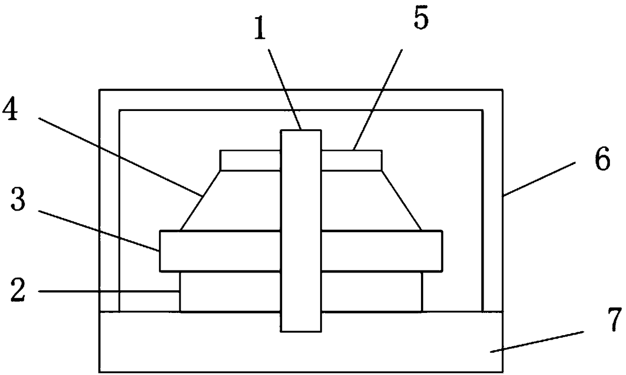
[0006] In addition, due to the different materials and density distribution of each part of the piezoelectric ceramic sheet, and there are errors in machining, it is difficult for the position of the center column to coincide with the center of mass of each part, resulting in eccentricity
[0007] Furthermore, due to the existence of the central column, the size and mass of the components are increased. The existing piezoelectric sensors generally have an outer diameter of 9mm and a weight of more than 5g, which limits the use of the device.

Method used


Image

  • High-precision piezoelectric sensor
  • High-precision piezoelectric sensor
  • High-precision piezoelectric sensor

Examples


Embodiment 1

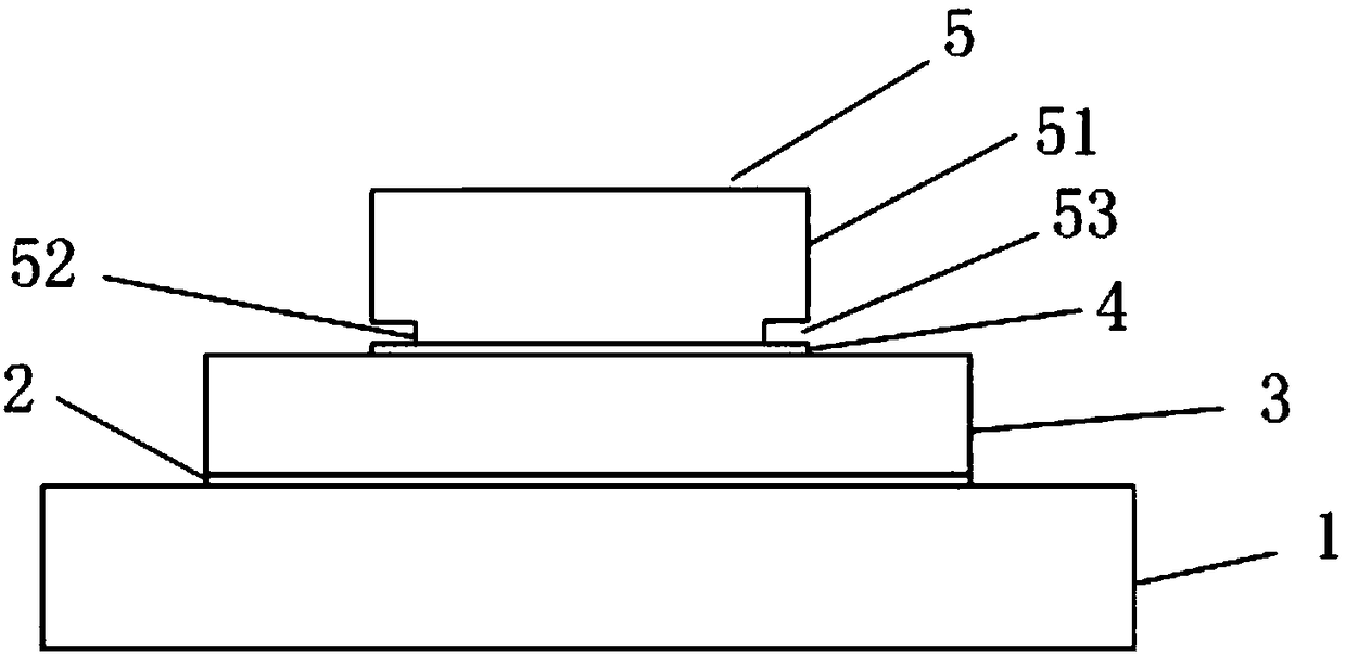
[0058] A high-precision piezoelectric sensor, such as figure 2 As shown, including a base 1, a first adhesive layer 2, a piezoelectric film layer 3, a second adhesive layer 4 and a mass 5 arranged on the base 1 in sequence;

[0059] The mass block 5 includes a body 51, a raised portion 52 at the bottom of the body 51, and a vacant portion 53 at the edge of the raised portion 52, the raised portion 52 is located on the axis of the mass block 5, and the body 51 is Cylindrical, its diameter is 4mm, and its height is 2.8mm, and described protrusion 52 is cylindrical, and its diameter is 2.5mm, and its height is 0.2mm, and described mass block 5 is made of copper, tungsten or tungsten copper, and its The weight is 0.32g;

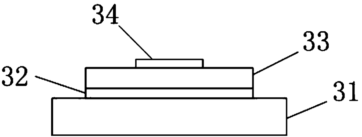
[0060] The piezoelectric film layer 3 includes a support body, a first electrode, a piezoelectric film and a second electrode arranged on the support body in sequence, wherein the first electrode and the second electrode are both made of Pt, and both Both have...

Embodiment 2

[0064] A high-precision piezoelectric sensor, such as Figure 5 As shown, including a base 1, a first adhesive layer 2, a piezoelectric film layer 3, a second adhesive layer 4 and a mass 5 arranged on the base 1 in sequence;

[0065] The mass block 5 includes a body 51, a raised portion 52 at the bottom of the body 51, and a vacant portion 53 at the edge of the raised portion 52, the raised portion 52 is located on the axis of the mass block 5, and the raised portion 52 includes a first raised portion 521 at the bottom of the body 51 and a second raised portion 522 at the bottom of the first raised portion 521, the body 51, the first raised portion 521 and the second raised portion 522 are all Cylindrical, the diameter of the body 51 is 4mm, the height is 2.8mm, the diameter of the first protrusion 521 is 3mm, the diameter of the second protrusion 522 is 1.5mm, and the mass block 5 is made of copper, tungsten or tungsten copper Made, its weight is 0.5g;

[0066] The piezoele...

Embodiment 3

[0070] A high-precision piezoelectric sensor, such as Figure 6 and Figure 7 As shown, including a base 1, a first adhesive layer 2, a piezoelectric film layer 3, a second adhesive layer 4 and a mass 5 arranged on the base 1 in sequence;

[0071] The mass block 5 includes a body 51, a plurality of protrusions 52 located at the bottom of the body 51, and a plurality of vacant parts 53 located at the edge of the protrusions 52, wherein the protrusions 52 and the cavities 53 criss-cross, the The body 51 is cylindrical, with a diameter of 4 mm and a height of 2.8 mm. Both the raised portion 52 and the vacant portion 53 have a width of 0.5 mm and a height of 0.2 mm. The mass 5 is made of copper, tungsten or tungsten copper Made, its weight is 0.4g;

[0072] The piezoelectric film layer 3 includes a support body, a first electrode, a piezoelectric film and a second electrode arranged on the support body in sequence, wherein the first electrode is made of Pt with a thickness of 15...


PUM


Abstract

The invention discloses a high-precision piezoelectric sensor. The high-precision piezoelectric sensor comprises a base, a first adhesive layer, a piezoelectric film layer, a second adhesive layer anda mass block, wherein the first adhesive layer, the piezoelectric film layer, the second adhesive layer and the mass block are arranged on the base in sequence; the mass block comprises a body, at least one protruding part located at the bottom of the body and at least one vacancy part adjacent to the protruding part; the protrusion part is in contact with the second adhesive layer, and the height of the vacancy part is larger than the thickness of the second adhesive layer. The piezoelectric film layer is laminated on the base through the first adhesive layer, and the mass block is stacked on the piezoelectric film layer through the second adhesive layer, so that the piezoelectric film layer, the first adhesive layer and the second adhesive layer are connected; a center column does not need to be arranged, the problem that the mass of a traditional compression type acceleration sensor is eccentric can be avoided, mechanical parts are reduced, and the resonance frequency and uniformity of the device are further adjusted. Furthermore, the vacancy part can be arranged at the bottom of the mass block, so that the precision of the device is improved by reducing the contact area between the mass block and the piezoelectric film layer and reducing the weight of the mass block.

Description

technical field [0001] The invention relates to the technical field of sensors, in particular to a high-precision piezoelectric sensor. Background technique [0002] Piezoelectric sensors are sensors based on the piezoelectric effect. Piezoelectric sensors can measure various dynamic forces, mechanical shocks and vibrations, convert force or deformation into electrical signals, and are widely used in acoustics, medicine, mechanics, navigation and other fields. [0003] Lead zirconate titanate (PZT) is a PbZrO 3 and PbTiO 3 PZT is the most widely used piezoelectric material in existing piezoelectric sensors because of its excellent piezoelectric and dielectric properties. Among them, if the ratio of Zr / Ti in PZT changes or one or two other trace elements (such as antimony, tin, manganese, tungsten, etc.) are added, its performance will also change. [0004] PZT piezoelectric acceleration sensor is a kind of PZT piezoelectric sensor. It is mainly divided into two categori...

Claims


Application Information

Patent Timeline
Patent Type & Authority Applications(China)
IPC IPC(8): G01D5/14G01P15/09
CPCG01D5/14G01P15/09
Inventor 陈显锋
Owner 佛山市卓膜科技有限公司
Learn More