
Flow control valve

A technology of flow control valve and valve opening, which is applied in the direction of flow control, flow control using electric devices, non-electric variable control, etc., and can solve problems such as inability to quickly supply hot water to users and low response speed

Inactive Publication Date: 2010-10-06
KYUNGDONG NETWORK
View PDF0 Cites 3 Cited by
  • Summary
  • Abstract
  • Description
  • Claims
  • Application Information

AI Technical Summary

Problems solved by technology

Since the flow rate is controlled through a continuous feedback process between the flow sensor 40, the control unit 80, and the flow control valve 20 to reduce the flow rate to a desired level, hot water of a desired temperature cannot be quickly supplied to users due to low response speed

Method used


Image

  • Flow control valve
  • Flow control valve
  • Flow control valve

Examples


Embodiment Construction

[0024] The configuration and operation of a preferred embodiment of the present invention will be described in detail below with reference to the accompanying drawings.

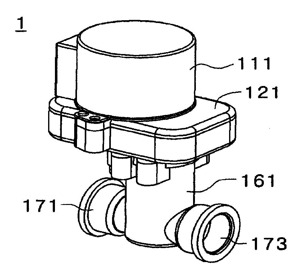
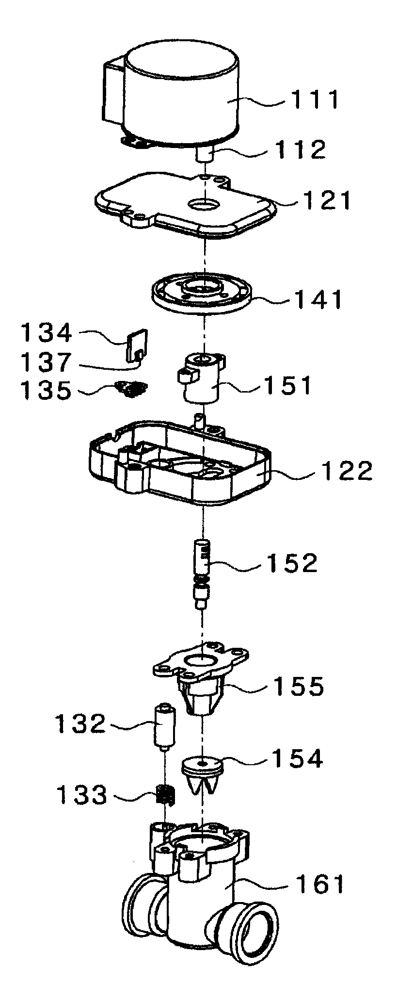
[0025] figure 2 is a perspective view illustrating the appearance of the flow control valve according to the embodiment of the present invention. image 3 yes figure 2 An exploded perspective view of the flow control valve shown. Figure 4 yes figure 2 Cross-sectional view of the flow control valve shown.

[0026] The flow control valve 1 includes: a motor 111, which can rotate in both directions; a switch part 154, which reciprocates vertically by the rotation of the motor 111, to control the opening ratio of the passage; a position changing part, whose position is related to the switch by the rotation of the motor 111. The part 154 is integrally changed; and a valve opening ratio sensing unit which senses the opening ratio of the switching part 154 from the output voltage which changes with the posit...


PUM


Abstract

The present invention relates to a flow control valve that is capable of rapidly supplying hot water at a user's desired temperature by promptly controlling the opening rate of a valve depending on the flow of supplied direct water. In order to implement this, the flow control valve according to the present invention includes a motor that rotates in both directions; an opening and closing member that reciprocates by rotation of the motor to control the opening rate of a channel; a position varying member of which a position varies integrally with the opening and closing member by the rotation of the motor; and a valve opening rate sensing unit that senses the opening rate of the valve from an output voltage varying depending on the position of the position varying member.

Description

technical field [0001] The present invention relates to a flow control valve, and more particularly, to a flow control valve installed in a boiler or a water heater and capable of controlling the flow of direct water supplied to a heat exchanger. Background technique [0002] Generally, a flow control valve capable of controlling the flow of water supplied through a direct water pipe is provided in a boiler or a water heater that supplies hot water. [0003] figure 1 is a schematic diagram showing a hot water supply system provided with a known flow control valve. refer to figure 1 , the hot water supply system includes: a direct water pipe 10 through which direct water flows; a flow control valve 20 which controls the flow of direct water supplied through the direct water pipe 10; a direct water temperature sensor 30 which senses the The temperature of the direct water at 20; the flow sensor 40, which is used to measure the flow of the direct water flowing through the di...

Claims


Application Information

Patent Timeline
Patent Type & Authority Applications(China)
IPC IPC(8): F16K31/04G05D7/06H01F7/02
CPCF16K31/04G05D7/0635F16K37/00
Inventor 金时焕
Owner KYUNGDONG NETWORK
Learn More