Condensing well for breathing tube

A technology of condensation traps and hoses, which is applied in the field of condensation traps of breathing hoses, and can solve the problems that condensation traps cannot be installed and condensed water cannot be discharged.

Inactive Publication Date: 2010-10-13
德尔格医疗控股有限责任公司
View PDF4 Cites 12 Cited by
  • Summary
  • Abstract
  • Description
  • Claims
  • Application Information

AI Technical Summary

Problems solved by technology

This means that the condensation trap cannot be installed anywhere on the breathing hose. This disadvantage often leads to the fact that the condensation trap cannot be installed at the lowest point of the breathing hose, so that an optimal and reliable discharge of condensate from the breathing hose cannot be guaranteed.

Method used


Image

  • Condensing well for breathing tube
  • Condensing well for breathing tube
  • Condensing well for breathing tube

Examples


Embodiment Construction

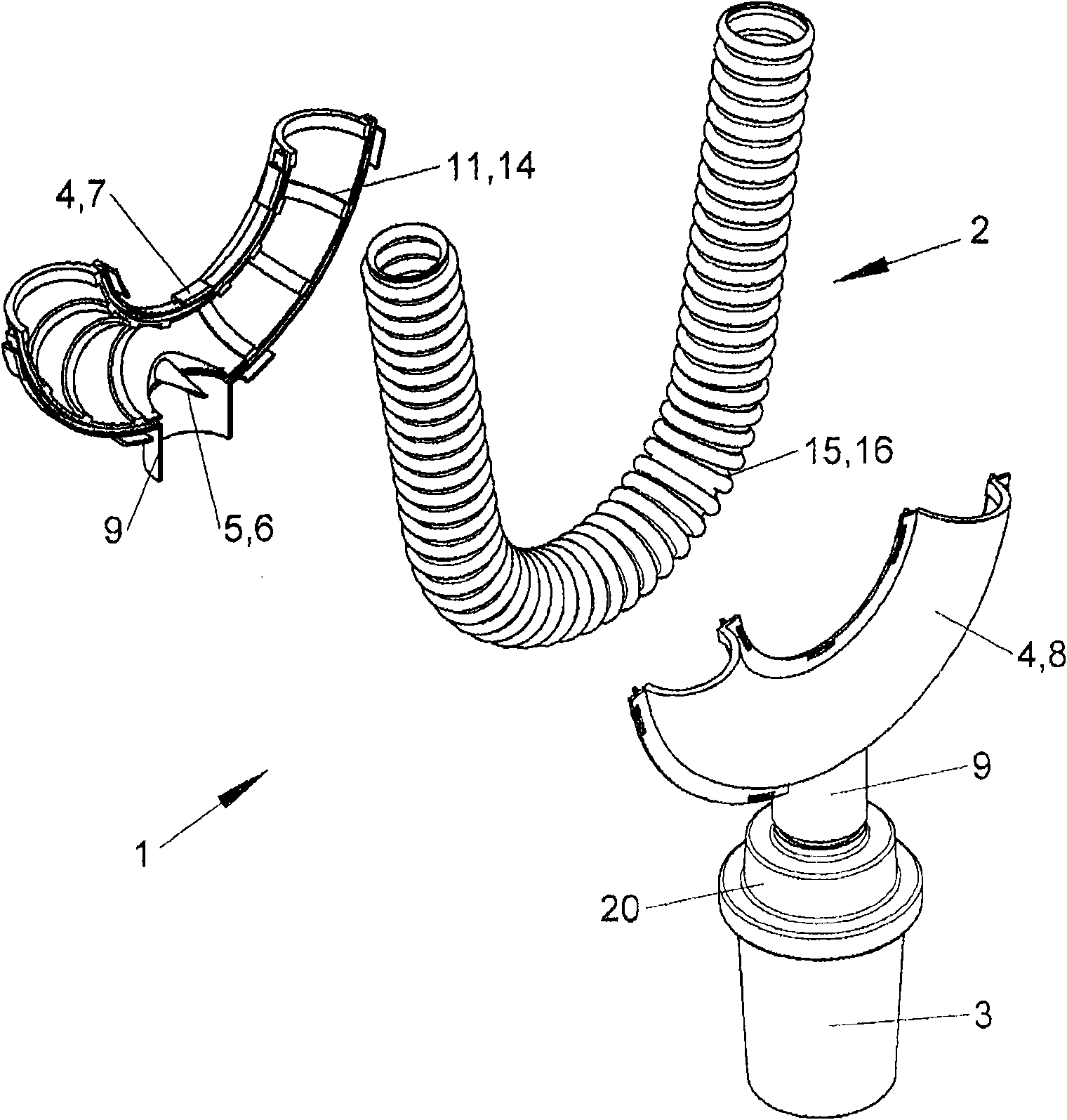
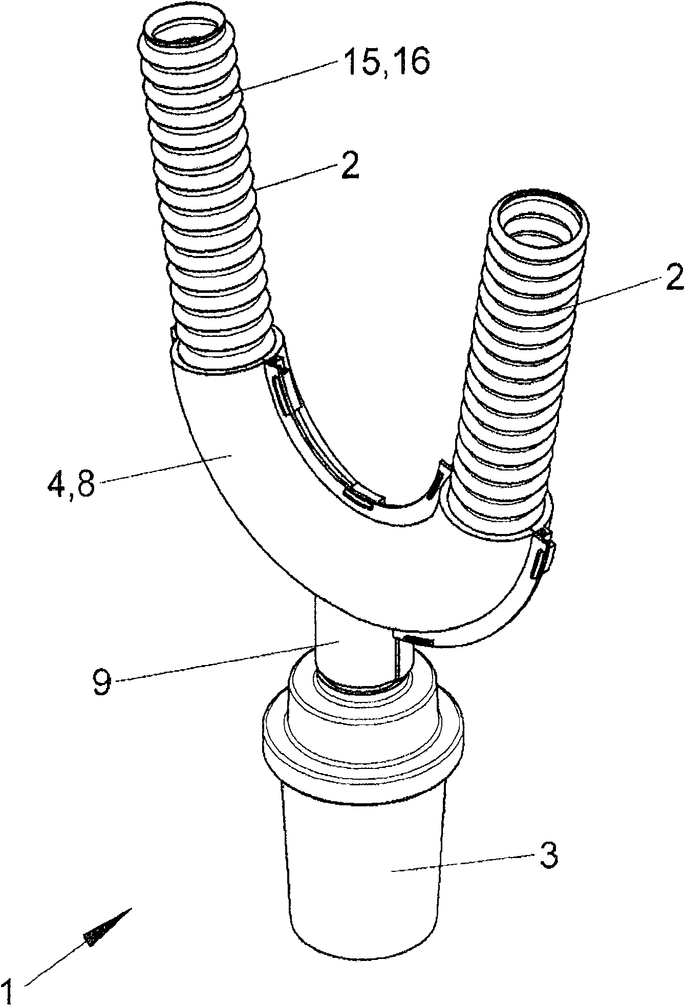
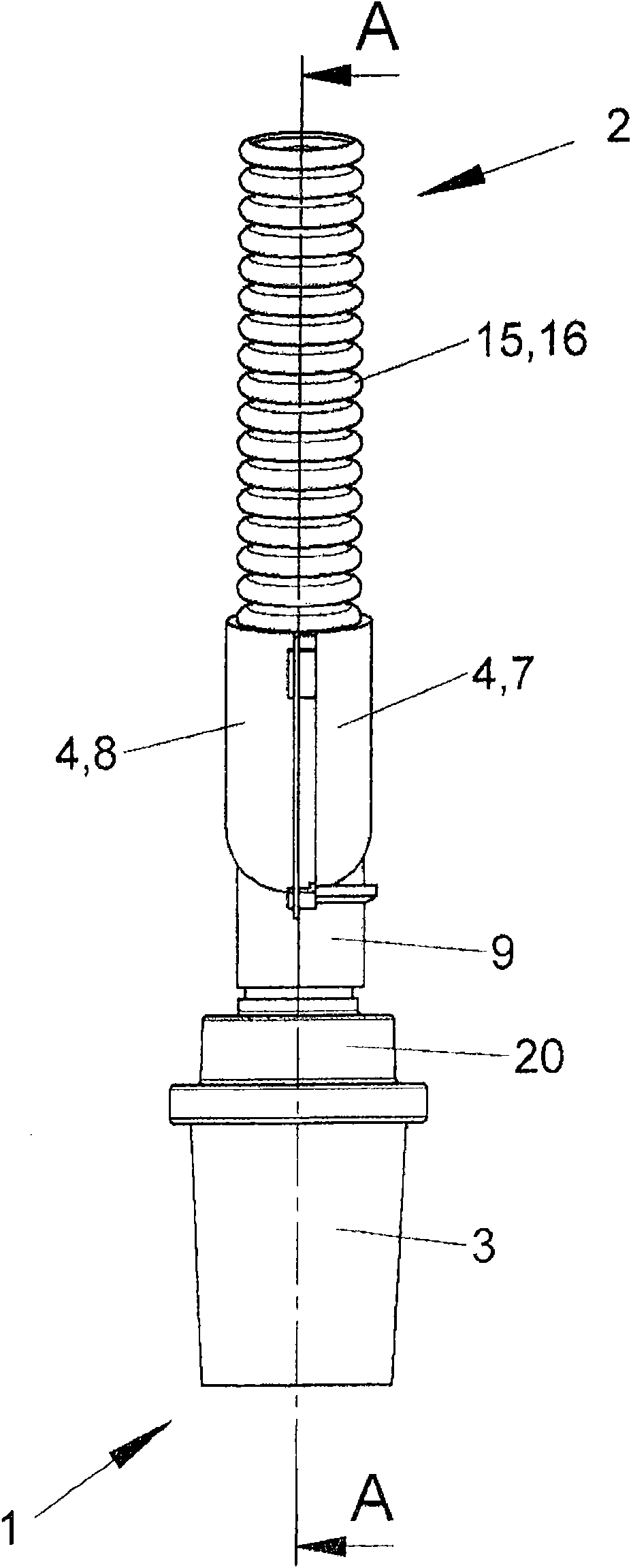
[0035] Figures 1 to 5 The condensation trap 1 shown is used to drain condensation from the breathing hose 2 of the breathing system. The condensation trap 1 thus prevents a large amount of condensed water from accumulating in the breathing tube, thereby preventing an increase in the air resistance in the breathing tube 2 or the penetration of condensed water into the lungs of the breathing patient.

[0036] The condensation trap 1 comprises a collector 3 for collecting condensed water and means 4 for fastening the collector 3 to the breathing hose 2 . The tool 4 consists of a first half shell 7 and a second half shell 8 ( figure 1 , 2 , 3 and 5). On the first half shell 7 there is a tool 5 for processing a hole in the breathing hose 2, which tool is made into a punch 6 ( figure 1 , 6 and 7), the breathing hose 2 made of plastic and flexible has a tangential groove 15 formed as an annular groove 16 ( Figures 1 to 5 ). The first and second half-shells 7, 8 have a U-shap...


PUM


Abstract

The invention relates to a condensing well for a breathing tube, a breathing system and a manufacturing method thereof. The well is characterized in that the manufacturing cost is low and the mounting position can be the lowest position on the breathing tube so as to reliably discharge the condensate water generated in the breathing tube when the artificial respiration is performed on the patients.

Description

technical field [0001] The invention relates to a condensation trap according to the preamble of claim 1 and a breathing system according to the preamble of claim 11 as well as a breathing system according to the preamble of claim 12 with a condensation trap A method for making a breathing hose or a breathing system. Background technique [0002] Ventilators are used as medical devices for artificial respiration of patients. The patient's artificial respiration air is delivered to the patient through a hose system. [0003] During the artificial respiration of the patient with the ventilator, moisture condensation occurs in the breathing system, and condensation water is formed in the breathing tube. This condensed water causes increased air resistance in the hose system and can enter the patient's lungs during artificial respiration. In order to prevent this from happening, condensation traps are installed on the breathing hose to collect the condensed water that forms i...

Claims


Application Information

Patent Timeline
Patent Type & Authority Applications(China)
IPC IPC(8): A61M16/08A61M16/20
CPCA61M16/0808A61M16/0816
Inventor A·赫希克C·本特鲁普M·泽尔克T·赖因博思
Owner 德尔格医疗控股有限责任公司
Why Eureka
Try Eureka