
Sludge-sucking robot

A robot and silt technology, applied in the direction of earth moving machine/shovel, mechanically driven excavator/dredger, construction, etc. The effect of saving the cost of dredging

Active Publication Date: 2010-10-13
杭州亿脑新融科技集团有限公司
View PDF5 Cites 8 Cited by
  • Summary
  • Abstract
  • Description
  • Claims
  • Application Information

AI Technical Summary

Problems solved by technology

[0002] At present, for small and medium-sized water areas, the main dredging method is to drain the water, and use excavators or dredgers to carry out dredging work directly in the absence of water. It has to be solved by excavating a temporary river channel. The engineering volume is large and cumbersome, and it will also make the dredging target unable to carry out work and production for a long period of time, resulting in certain economic losses. Therefore, this working method produces The efficiency is low, the labor intensity is high, the method is primitive, and in many cases, due to the depth of the riverbed and the topography, it is impossible to use large-scale construction machinery for mechanized operations
There is also the use of sludge suction equipment for underwater work, but the existing underwater sludge suction equipment is generally installed on floating platforms or ships for use, requiring one to several operators for manual manipulation, heavy physical labor and expensive dredging The cost makes these traditional dredging products unable to meet the needs of today's market, and does not conform to the concept of energy saving and environmental protection

Method used


Image

  • Sludge-sucking robot
  • Sludge-sucking robot
  • Sludge-sucking robot

Examples


Embodiment Construction

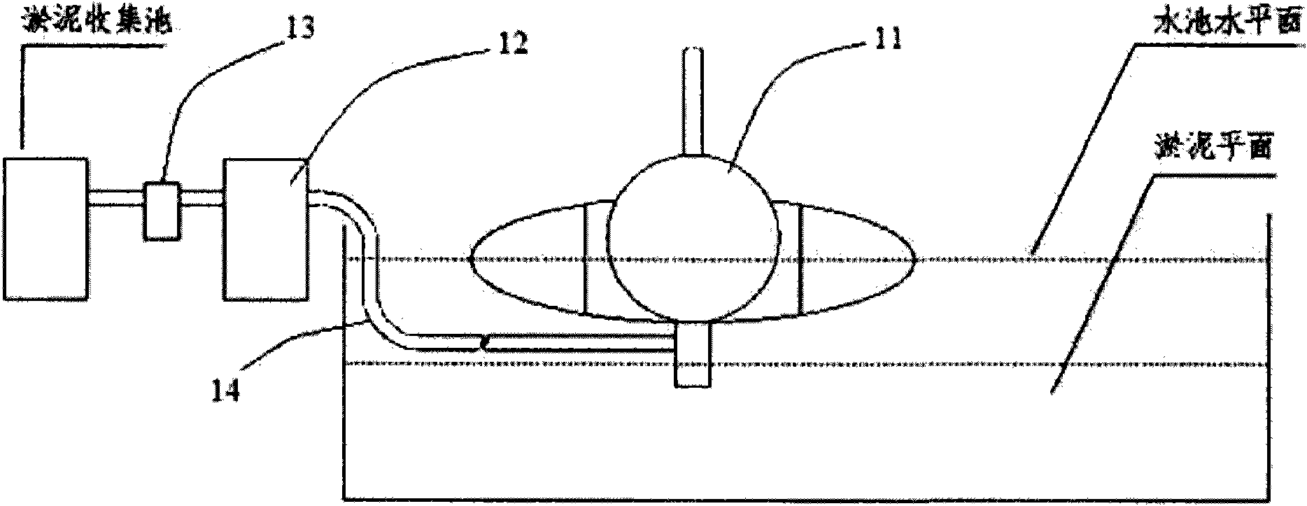
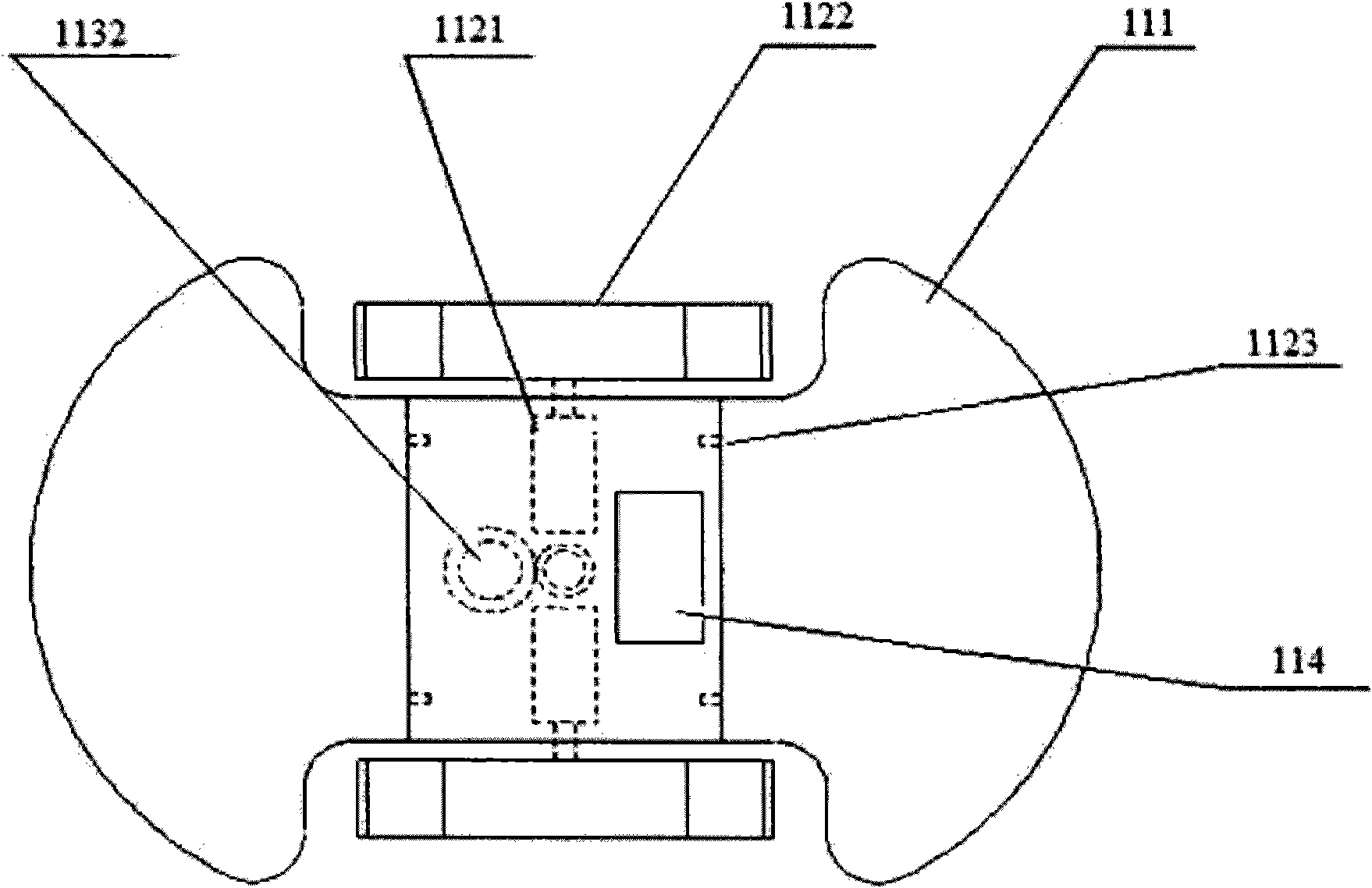
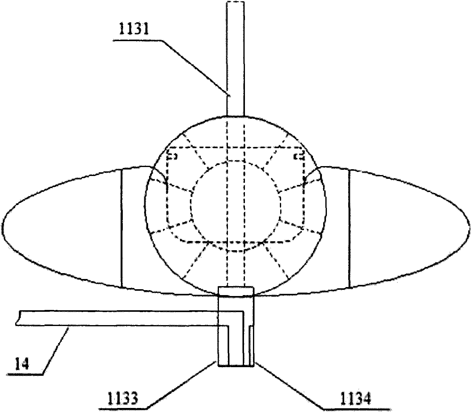
[0017] see Figure 1-3 , The mud suction robot 1 provided by the present invention includes a suction pipe guiding assembly 11 , a suction pipe winding assembly 12 , a mud suction assembly 13 and a suction pipe 14 . The suction pipe guide assembly 11 is the intelligent core of the mud suction robot 1. This assembly can automatically realize forward, backward, left turn and right turn movements in the pool, and can automatically detect the depth of the mud suction and extend the suction pipe 14. into the silt, and send instructions to the silt suction assembly 13 and the suction pipe winding assembly 12 on the bank to control their working modes, so as to automatically suck the silt in the water treatment pond into the designated silt collection pond.

[0018] The straw guiding assembly 11 includes a buoyancy component 111 , an intelligent walking component 112 , a straw depth adjusting component 113 and an intelligent control center 114 .

[0019] The buoyancy component 111 c...


PUM


Abstract

The invention relates to a sludge-sucking device, in particular to a robot which can fully automatically suck sludge. The sludge-sucking robot comprises a suction pipe coiling assembly, a sludge pumping assembly, a suction pipe and a suction pipe guide assembly, wherein the suction pipe guide assembly is the intelligent kernel of the sludge-sucking robot; and the suction pipe guide assembly can automatically realize forward, backward, left-turn and right-turn motions in a water tank, automatically detect the depth of sludge to be sucked, extend the suction pipe into the sludge, and give orders to the sludge pumping assembly and the suction pipe coiling assembly on the bank to control the working modes so as to automatically suck the sludge from the water treating tank to a specified sludge collecting tank. Compared with the prior art, the sludge-sucking robot can automatically and thoroughly clean underwater sludge in an unattended mode, thereby thoroughly changing the traditional sludge-sucking mode, emancipating people from exhausting labor, saving the high dredging cost, and being a scientific, energy-saving and environment-friendly invention in deed.

Description

technical field [0001] The invention relates to a sludge suction device, in particular to a robot capable of fully automatic sludge suction. Background technique [0002] At present, for small and medium-sized water areas, the main dredging method is to drain the water, and use excavators or dredgers to carry out dredging work directly in the absence of water. It has to be solved by excavating a temporary river channel. The engineering volume is large and cumbersome, and it will also make the dredging target unable to carry out work and production for a long period of time, resulting in certain economic losses. Therefore, this working method produces The efficiency is low, the labor intensity is high, the method is primitive, and in many cases, due to the depth of the riverbed and the topography, it is impossible to use large-scale construction machinery for mechanized operations. There is also the use of sludge suction equipment for underwater work, but the existing underw...

Claims


Application Information

Patent Timeline
Patent Type & Authority Applications(China)
IPC IPC(8): E02F3/88E02F3/92E02F5/28
Inventor 应放天应佳伟朱明春
Owner 杭州亿脑新融科技集团有限公司
Learn More