Supercharge Your Innovation With Domain-Expert AI Agents!

Load cell for detecting supporting force on load-bearing support element

A technology for load cells and support components, which is applied in the direction of weighing equipment, special scales, and force measurement using elastically deformable components, and can solve problems such as contamination of support components and damage to sensitive measuring instruments

Active Publication Date: 2010-10-13
WLKA ALEXANDER WIEGAND SE & CO KG
View PDF3 Cites 8 Cited by
  • Summary
  • Abstract
  • Description
  • Claims
  • Application Information

AI Technical Summary

Problems solved by technology

Contamination of the support elements is particularly severe in this area, which can damage sensitive measuring instruments

Method used


Image

  • Load cell for detecting supporting force on load-bearing support element
  • Load cell for detecting supporting force on load-bearing support element
  • Load cell for detecting supporting force on load-bearing support element

Examples


Embodiment Construction

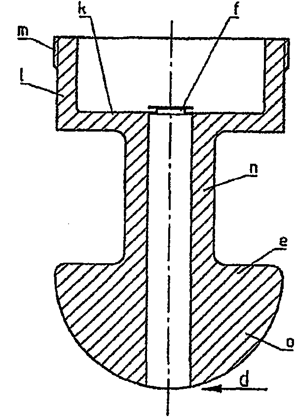
[0032] according to image 3 , the load cell consists of a steel rust-resistant deformable part e, the strain of which is induced by the force to be measured is not detected by means of strain gauges glued to this part, but by means of strain-sensitive resistors manufactured using thin-film technology . This has the advantage of high long-term stability, since thin-film resistors produced in thin-film technology are not glued to the carrier, but are adhered to the carrier as a composite of atoms by cohesive sputtering.

[0033] according to Figure 4a , 4b , thin-film resistors are provided on the end faces of the flat cylindrical carrier f initially separated from the load cell, the material of which corresponds to that of the deformed part, or at least exhibits similar thermal expansion properties. During the processing of the load cell, the carrier part and the deformation part are adhesively bonded together at their outer edge g by means of welding laser or electron bea...


PUM


Abstract

The invention relates to a load cell for detecting supporting force on load-bearing support element for detecting the supporting force transmitted by the load-bearing support element. The load cell comprises a measuring portion which deforms under the supporting force and transverse forces in a direction deviating from the supporting force to form part of the support element with the same. A plurality of thin-film resistors are arranged at the measuring portion and exhibit a reaction proportional to strain, and reactions of which proportional to transverse forces cancel each other. The thin-film resistors are fixedly connected to the measuring portion. The reactions can be cancelled by arranging the thin-film resistors in the measuring portion or processing the detected signals.

Description

technical field [0001] The invention relates to a load cell for detecting bearing forces in a bearing element, in particular for use in lifting vehicles, mobile hoisting winches, mobile drilling platforms, self-propelled gun mounts or similar devices. Background technique [0002] figure 1 A lifting vehicle is schematically shown in , resting on feet a, which serve as support elements to ensure uprightness during operation. The support element a is usually arranged at the end of a telescopic support arm b fixed to the vehicle bed c. Where the crane is located, the entire vehicle is lifted hydraulically with the aid of support elements. The wheels are not in contact with the ground. [0003] When the forces are transmitted vertically to the ground via the support element, the weight distribution can be determined, whereby the center of gravity of the vehicle, in particular when lifting a load, can also be determined, which in turn can be used to determine the tipping point...

Claims


Application Information

Patent Timeline
Patent Type & Authority Applications(China)
IPC IPC(8): G01L1/22
CPCG01L1/2231G01G3/14G01G19/12
Inventor 约希姆·霍斯·范·沃尔夫拉姆斯多尔夫奥利弗·约斯特克劳斯·哈利斯蒂芬·阿门特
Owner WLKA ALEXANDER WIEGAND SE & CO KG
Features
  • R&D
  • Intellectual Property
  • Life Sciences
  • Materials
  • Tech Scout
  • Unparalleled Data Quality
  • Higher Quality Content
  • 60% Fewer Hallucinations
Learn More