Touch display device

A touch display device and display module technology, applied in static indicators, nonlinear optics, optics, etc., can solve problems such as poor reliability, difficulty in rework, and bubbles in optical glue, and achieve convenient assembly and rework, The effect of improving the assembly positioning accuracy and reducing the risk of damage

Inactive Publication Date: 2011-11-16
华映视讯(吴江)有限公司 +1
View PDF0 Cites 0 Cited by
  • Summary
  • Abstract
  • Description
  • Claims
  • Application Information

AI Technical Summary

Problems solved by technology

However, after a long time of use, the optical glue will have a problem of poor reliability
In addition, during the assembly process, the optical glue may produce air bubbles that cause abnormal scattering of light
Furthermore, the method of using optical glue still has the problem that the overall thickness is too thick and it is not easy to rework when the bonding is not good.
In particular, if only the touch panel is damaged and the display panel is still in good condition, it will be difficult to replace the touch panel

Method used


Image

  • Touch display device
  • Touch display device
  • Touch display device

Examples


Embodiment Construction

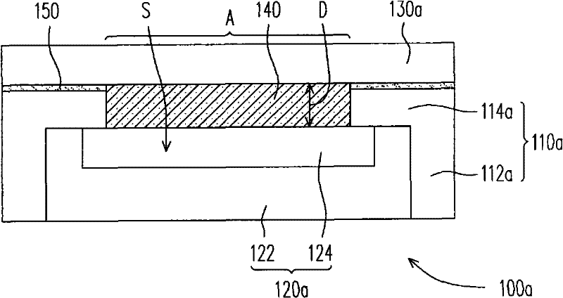
[0021] figure 1 It is a schematic diagram of a touch display device according to an embodiment of the present invention. Please refer to figure 1 , in this embodiment, the touch display device 100a includes a frame 110a , a display module 120a , a touch module 130a and an elastic optical film 140 .

[0022] In detail, the frame 110a has a vertical side wall portion 112a and a horizontal extension portion 114a to form a receiving space S. As shown in FIG. Wherein, the horizontal extension part 114a is connected with the vertical side wall part 112a, and the horizontal extension part 114a is extended from the vertical side wall part 112a toward the direction perpendicular to its extension, and the vertical side wall part 112a located in the frame 110a and the horizontal extension The internal space of the portion 114a is defined as the accommodation space S. In this embodiment, the material of the frame 110a is mainly light metal with sufficient mechanical strength, such as m...


PUM

PropertyMeasurementUnit
refractive indexaaaaaaaaaa

Abstract

The invention relates to a touch display device which comprises a display module, a touch module and an elastic optical film, wherein the touch module is configured above the display module; the elastic optical film has no viscosity and is positioned between the touch module and the display module; and when the touch module is assembled above the display module, the elastic optical film generateselastic deformation to absorb a clearance of a surface between the touch module and the display module.

Description

technical field [0001] The present invention relates to a display device, and in particular to a touch display device. Background technique [0002] A touch panel is a human-machine interface that has been widely accepted by the public. The touch panel can be assembled on various types of flat-panel displays, so that the flat-panel displays can display pictures and input operation information. [0003] Generally speaking, a touch display device mainly includes a display panel and a touch panel. In a known touch display device, the touch panel and the display panel are bonded together through double-sided adhesive tape. However, since the double-sided tape is only pasted around the display panel and the touch panel, there is an air layer between the touch panel and the display panel. Light in the environment will be reflected in this air layer, resulting in a decrease in the contrast and visibility of the display panel. [0004] In order to improve the above disadvantages...

Claims


Application Information

Patent Timeline
Patent Type & Authority Patents(China)
IPC IPC(8): G02F1/133G02F1/13
Inventor 姚博仁
Owner 华映视讯(吴江)有限公司
Why Eureka
Try Eureka