Manufacturing unit for integrated thin film solar cells

A technology for thin-film solar cells and manufacturing devices, which is applied in the direction of fine working devices, manufacturing tools, and final product manufacturing. Excellent linear effect

Inactive Publication Date: 2010-10-13
MITSUBOSHI DIAMOND IND CO LTD
View PDF6 Cites 9 Cited by
  • Summary
  • Abstract
  • Description
  • Claims
  • Application Information

AI Technical Summary

Problems solved by technology

[0016] Therefore, in order to fix the peeling degree of the thin film, it is necessary to adjust the load on the pressing blade tip in combination with the properties of the film, etc., but the control mechanism of

Method used


Image

  • Manufacturing unit for integrated thin film solar cells
  • Manufacturing unit for integrated thin film solar cells
  • Manufacturing unit for integrated thin film solar cells

Examples


Embodiment Construction

[0047] Hereinafter, details of the present invention will be described in detail based on the drawings showing embodiments of the present invention.

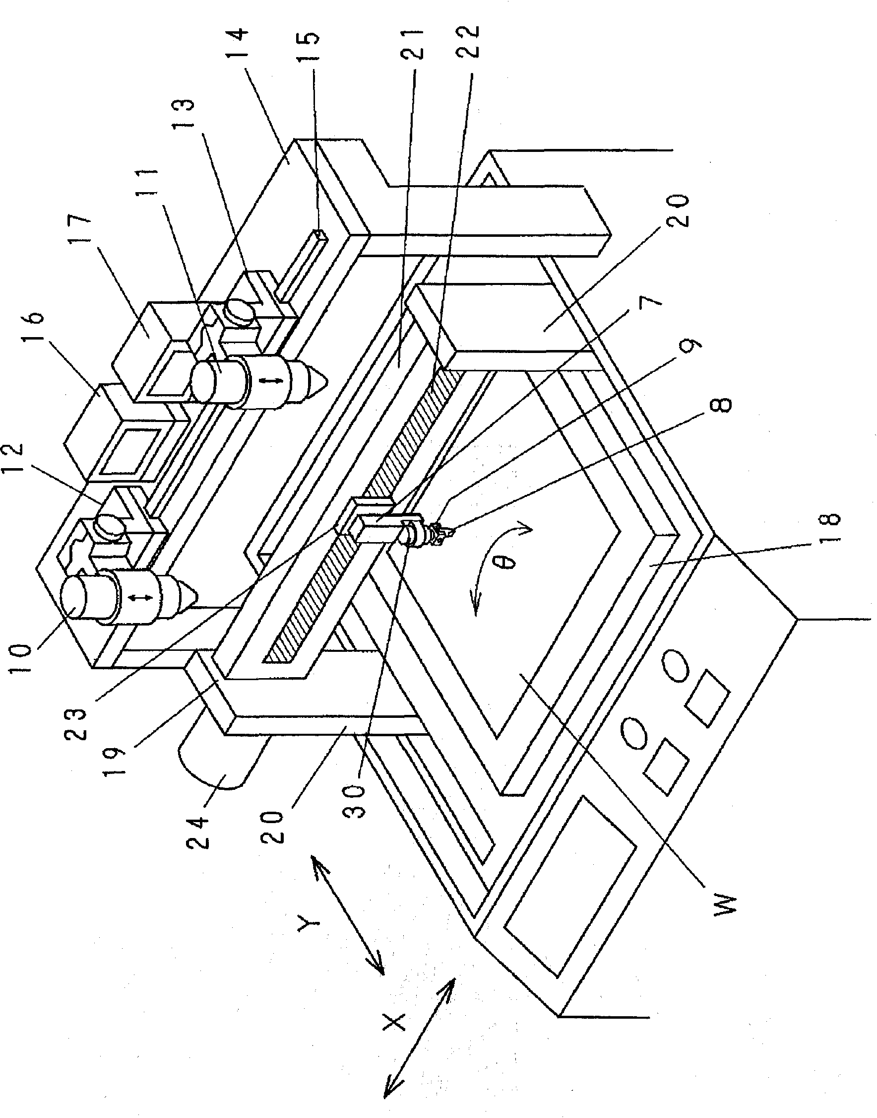
[0048] figure 1 It is a perspective view showing an embodiment of the manufacturing apparatus of the integrated thin film solar cell of the present invention. The device has a platform 18 that can move in the horizontal direction (Y direction) and can rotate 90 degrees and an angle θ in the horizontal plane. The platform 18 essentially forms a supporting mechanism for the solar cell substrate W.

[0049]The bridge body (bridge) 19 is arranged across the mode on the platform 18, and the bridge body 19 includes supporting columns 20, 20 on both sides of the clamping platform 18, and a guide bar (guide bar) extending in the X direction. )twenty one. The bracket supporting body 23 is movably installed along the guide 22 formed on the guide bar 21 , and is moved in the X direction by the rotation of the motor 24 .

[0050] A scri...


PUM


Abstract

The object of the present invention is to provide a manufacturing unit for solar cells with which high quality integrated thin film solar cells with a constant trench width can be manufactured at a high yield. The means used for achieving the object of the present invention are a support for supporting a thin film solar cell substrate (W), a scribing head (7) for holding a tool for creating a trench (8) via a means for applying pressure, and a moving means for moving the substrate W and the scribing head (7) relative to each other are provided, and the means for applying pressure is formed of a voice coil motor (30) where the amount of current flowing into the motor can be controlled by a control portion S.

Description

technical field [0001] The invention relates to a manufacturing device of a chalcopyrite compound-based integrated thin-film solar cell. [0002] Here, the so-called chalcopyrite compound, except containing CIGS(Cu(In,Ga)Se 2 ), also contains CIGSS (Cu(In, Ga)(Se, S) 2 ), CIS (CuInS 2 )Wait. Background technique [0003] In a thin-film solar cell using a chalcopyrite compound semiconductor as a light-absorbing layer, it is usually an integrated structure in which a plurality of unit cells are connected in series on a substrate. [0004] A conventional method for producing a chalcopyrite compound-based integrated thin-film solar cell will be described. Figure 6 It is a schematic diagram showing the manufacturing steps of a CIGS thin film solar cell. First, if Figure 6 As shown in (a), on an insulating substrate 1 including soda lime glass (SLG, soda lime glass), etc., a Mo electrode layer 2 as a positive side lower electrode is formed by sputtering, and then the light a...

Claims


Application Information

Patent Timeline
IPC IPC(8): H01L31/18
CPCH01L27/1423B28D5/00B28D1/225Y02E10/541H01L21/67092H01L31/046Y02P70/50
Inventor 曾山正信
Owner MITSUBOSHI DIAMOND IND CO LTD
Why Eureka
Try Eureka