
Photoelectric trigger device based on thyristor switched capacitor

A technology of switching capacitors and photoelectric triggering, which is applied in harmonic reduction devices, flexible AC transmission systems, and AC networks to reduce harmonics/ripples, etc., and can solve the problems of low service life of circuit breakers and failure to meet reliable switching of capacitors Needs, large capacitive impact current and other problems, to achieve the effect of clear hierarchy, easy maintenance, simple and clear logic

Active Publication Date: 2010-10-13
CHINA EPRI SCIENCE & TECHNOLOGY CO LTD +3
View PDF5 Cites 4 Cited by
  • Summary
  • Abstract
  • Description
  • Claims
  • Application Information

AI Technical Summary

Problems solved by technology

[0002] At present, in the power system and industrial system, mechanical circuit breakers or other mechanical equipment are commonly used to switch capacitors, such as the Chinese utility with application number 01276142.7 A new type of patent, which discloses a multi-group cycle switching switch for high-voltage capacitors. Although it can achieve the purpose of switching capacitors to compensate for reactive power, it has the disadvantages of low service life of circuit breakers and large impact currents when switching capacitors.
The thyristor valve-based electronics (VBE) device commonly used in power electronic equipment is mainly used in thyristor-controlled reactor devices. For example, the Chinese invention patent with application number 200510102659.9 discloses a static var Compensator monitoring platform, which is well suited for reactor switching control, but when the switching object is a capacitor, it cannot meet the needs of reliable switching of capacitors due to different load characteristics

Method used


Image

  • Photoelectric trigger device based on thyristor switched capacitor
  • Photoelectric trigger device based on thyristor switched capacitor
  • Photoelectric trigger device based on thyristor switched capacitor

Examples


Embodiment Construction

[0022] The photoelectric trigger device of the present invention will be further described in detail below in conjunction with the accompanying drawings.

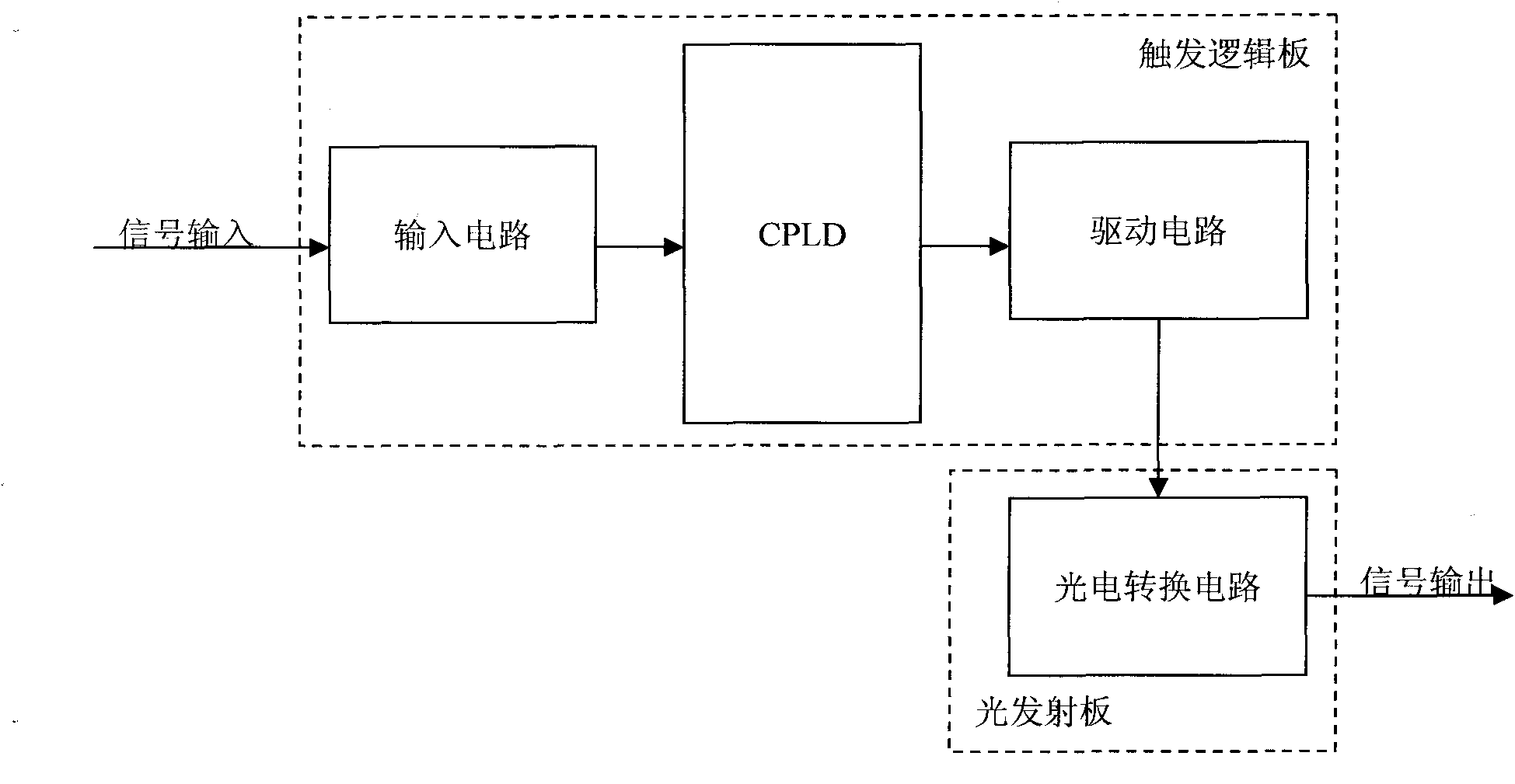
[0023] Such as figure 1 As shown, the photoelectric trigger device includes a trigger logic board, a light emitting board and a capacitor residual voltage detection device. The trigger logic board and the light emitting board respectively plugged into the chassis backplane realize signal transmission through the printed lines on the backplane. The trigger logic board is connected with the capacitor residual voltage detection device through a cable. When in use, it is necessary to connect the light emission board of the photoelectric trigger device with the trigger board (TE board) of the thyristor valve string through optical fibers, and connect the trigger logic board with the high-voltage thyristor switching capacitor through optical fibers and cables.

[0024] The trigger logic board includes an input circuit, a logic p...


PUM


Abstract

The invention relates to a photoelectric trigger device based on a high-voltage thyristor switched capacitor (TSC), which is respectively connected with a high-voltage thyristor switched capacitor and a trigger board of a thyristor valve string. The photoelectric trigger device comprises a trigger logic board, a light-emitting board and a residual capacitor voltage detection device, wherein the trigger logic board is respectively connected with the light-emitting board and the residual capacitor voltage detection device. The photoelectric trigger device adopts the logic processing unit on thetrigger logic board as the logic operation core to receive various control commands and angle signals, and the detection of the residual capacitor voltage is used as criteria of the phase angle and the valve string direction for the first input moment to complete the logic operation of Phase A, Phase B and Phase C, thereby making the hierarchy clear and the logic simple, and facilitating the maintenance and the follow-up upgrading and development.

Description

technical field [0001] The invention belongs to the field of power system controllers, and in particular relates to a photoelectric trigger device based on a high-voltage thyristor switching capacitor TSC. Background technique [0002] At present, in power systems and industrial systems, mechanical circuit breakers or other mechanical devices are commonly used to switch capacitors. Switching switch, although it can achieve the purpose of switching capacitors to compensate reactive power, but there are disadvantages such as short service life of the circuit breaker and large inrush current when switching capacitors. The thyristor valve-based electronics (VBE) device commonly used in power electronic equipment is mainly used in thyristor-controlled reactor devices. For example, the Chinese invention patent with application number 200510102659.9 discloses a static var A compensator monitoring platform, which is well suited for reactor switching control, but when the switching ...

Claims


Application Information

Patent Timeline
Patent Type & Authority Applications(China)
IPC IPC(8): H02J3/18H02J3/01
CPCY02E40/12Y02E40/10Y02E40/40
Inventor 李卫国林韩吴文宣赵刚刘宏陈金祥
Owner CHINA EPRI SCIENCE & TECHNOLOGY CO LTD
Learn More