Electric pressure cooker with sliding spring plate

An electric pressure cooker and shrapnel technology, applied in pressure cookers and other directions, can solve the problems of reducing the service life of the pressure switch, out of control of abnormal pressure control, failing to meet safety requirements, etc. Effect

Inactive Publication Date: 2010-10-20
广东威王集团顺德电器有限公司
View PDF7 Cites 3 Cited by
  • Summary
  • Abstract
  • Description
  • Claims
  • Application Information

AI Technical Summary

Problems solved by technology

Due to the fixed connection of the electric heating plate, shrapnel, and the middle layer, the above-mentioned technology cannot avoid possible abnormal noises. The pressure of the electric pressure cooker is relatively high during normal operation, and the requirements for the shrapnel are relatively high, which makes the manufacturing cost high. At the same time, the displacement of the pressure is controlled. Small, the abnormal pressure control is seriously out of control, the working stability is poor, and it cannot meet the requirements of safety regulations. With the prolongation of the use time, the working pressure will continue to decay, which will affect the cooking effect. In addition, the pressure switch is directly installed on the electric heating plate. The switch has high requirements, on the other hand it will greatly reduce the service life of the pressure switch

Method used


Image

  • Electric pressure cooker with sliding spring plate
  • Electric pressure cooker with sliding spring plate
  • Electric pressure cooker with sliding spring plate

Examples


Embodiment 1

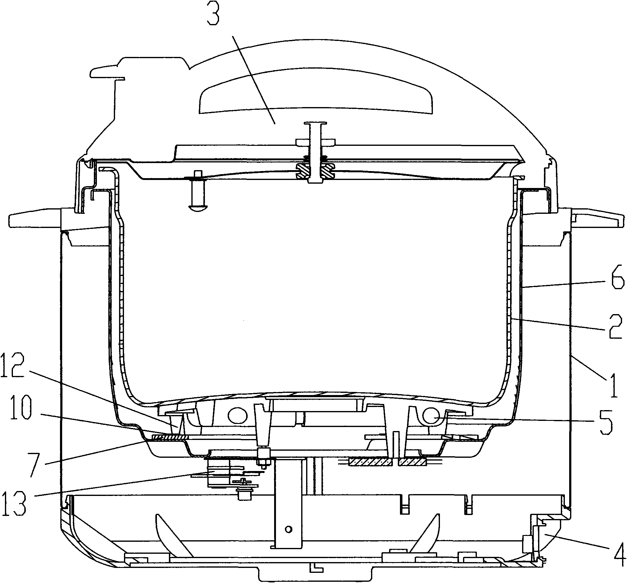
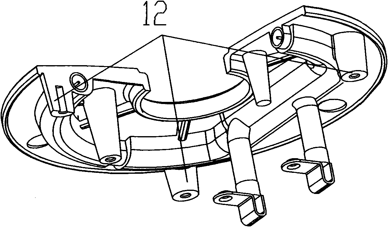
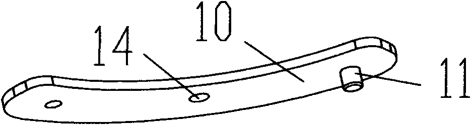
[0023] An electric pressure cooker with sliding shrapnel, such as figure 1 , figure 2 , image 3 and Figure 4 As shown, it includes a pot body 1, an inner pot 2, a pot cover 3, a base 4, and an electric heating plate 5. The inner pot 2 is placed in the pot body 1, the pot cover 3 is installed above the pot body 1, and the electric heating plate 5 is installed on the base. 4, there are 3 pairs of bosses 7 arranged on the inner bottom of the middle layer 6 by the side wall; the upper ends of the bosses 7 leave spaced holes 8 and fixing holes 9 alternately; The other end of the shrapnel 10 is provided with a boss 11, and the boss 11 is placed in the limit hole 8; the back of the electric heating plate 5 is provided with a bump 12 matching the boss 7, and the bump 12 is connected with the sliding shrapnel 10; The pressure switch 13 is directly installed on the outer bottom of the middle layer 6 . There are three pairs of said bosses 7; the bumps 12 are correspondingly matche...

Embodiment 2

[0025] With embodiment 1. The difference is: the sliding shrapnel is crescent-shaped. The bosses 7 are arranged in four pairs, and the bosses 7 are arranged in a quadrangular shape on the inner bottom of the middle layer 6 .

[0026] Working principle: When the power is turned on, the electric heating plate is heated, the water-containing food in the inner pot is heated and evaporated, and the steam generates pressure in the inner pot. Since the middle layer of the pot lid is rigidly connected, the pressure is transmitted to the electric heating plate through the inner pot, and the electric heating plate will The pressure is transmitted to the shrapnel, the shrapnel produces elastic deformation, the inner pot and the electric heating plate move downward at the same time, and the pressure switch is driven at the contact point of the electric heating plate with the pressure switch; when a certain displacement is reached, the pressure switch is disconnected to cut off the power s...


PUM


Abstract

The invention provides an electric pressure cooker with a sliding spring plate, which comprises a pot body, an inner pot, a pot cover, a base and an electric hot tray. The inner pot is arranged in the pot body, the electric hot tray is arranged in the base, and the inner bottom of the middle layer close to the sidewall is provided with an even number of convex plates; the sliding spring plate and the convex column on the electric hot tray are connected with the convex plates; and a pressure switch is arranged on the bottom of the outer side of the middle layer. The invention has the advantages of simple structure, easy manufacture, simple installation and maintenance and long service life. The pressure release value is 2-2.5 times of the working pressure, e.g. less than or equal to 200kPa. Moreover, the invention has a stable performance and can realize the precise pressure control and completely satisfy national requirements for safety.

Description

technical field [0001] The invention relates to the field of electric pressure cooker technology, and more specifically relates to the improvement of the electric pressure cooker technology. Background technique [0002] At present, there are many kinds of electric pressure cookers disclosed on the market, and the styles are also various, but the existing electric pressure cookers with elastic structure are all provided with elastic elements between the electric heating plate and the middle layer. Chinese patent "Elastic Support Device for Electric Pressure Cooker", patent number: 200920060890.X, discloses an elastic support device for electric pressure cooker, which includes an outer pot and shrapnel. The group includes two upwardly protruding ribs, each rib group is provided with a shrapnel, and the two parallel ribs of the rib group support the shrapnel by contacting the lower surface of the shrapnel. Through the setting of rib groups and independent elastic pieces, the ...

Claims


Application Information

Patent Timeline
Patent Type & Authority Applications(China)
IPC IPC(8): A47J27/08
Inventor 梁裕苏春冯国栋
Owner 广东威王集团顺德电器有限公司
Why Eureka
Try Eureka