Movable cover controlling device
A technology of control device and movable cover, which is applied to cooking utensil lids, cooking utensils, household appliances, etc., can solve the problems of electrical safety hazards, high production costs, and influence of temperature collection, etc., and achieve good control sensitivity and stability, temperature The effect of low control error, stable conversion relationship and repeatability
- Summary
- Abstract
- Description
- Claims
- Application Information
AI Technical Summary
Problems solved by technology
Method used
Image
Examples
Embodiment 1
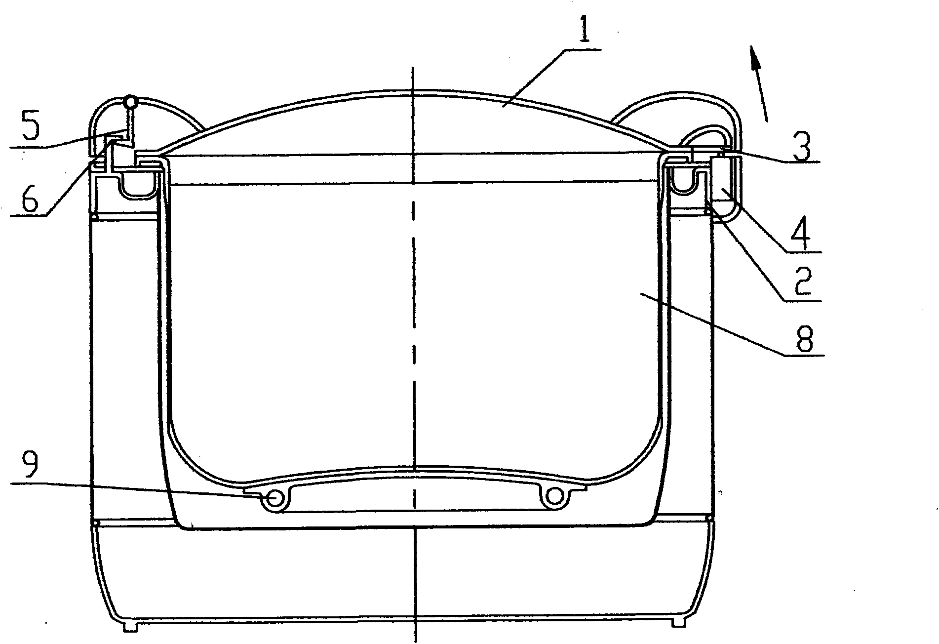
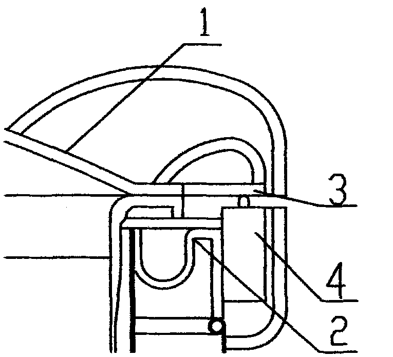
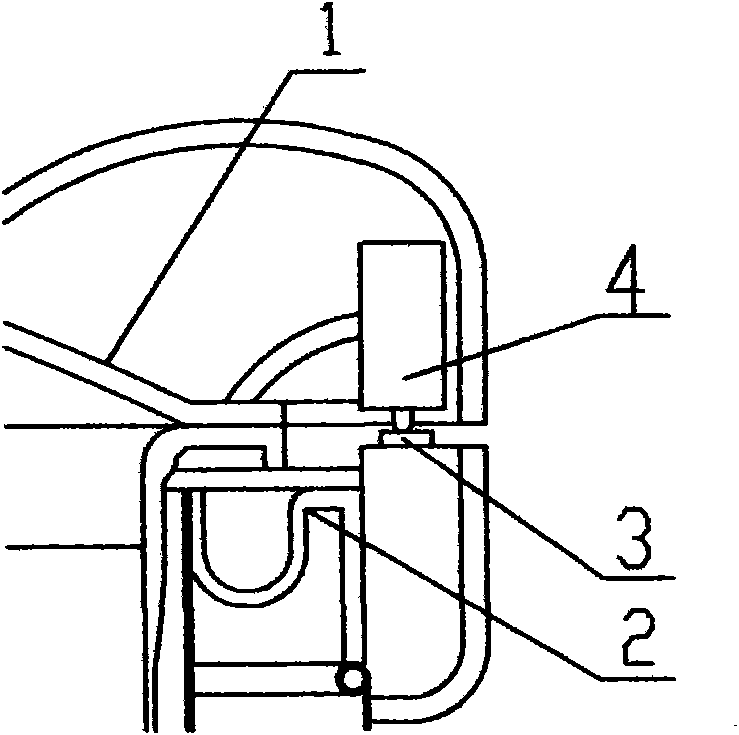
[0032] Embodiment 1: see attached figure 1 . On the side of the junction of the pot cover part 1 and the pot body part 2 ( figure 1 Right side in ), set the control mechanism. like figure 2 As shown, the transmission part 3 in the control mechanism is a rigid structural member, which is fixedly arranged on the pot cover part 1 or made into one with the pot cover part 1, so that it can move synchronously with the pot cover part 1. The switch 4 can be selected as a micro switch whose electrical parameters are about 200g·f on-off displacement force and about 0.1mm on-off displacement sensitivity. The switch 4 is arranged on the pot body part 2 below the transfer member 3 . The setting positions of the transmission part 3 and the switch 4 should satisfy: when the pot cover part 1 is fastened, the gravity of the pot cover part 1 touches the contact of the switch 4 through the transmission part 3, so that the switch 4 is in the open state. When the pot cover part 1 is driven b...
Embodiment 2
[0036] Embodiment 2: see specification attached Figure 7 . The fulcrum mechanism is arranged on the side where the pot cover part 1 and the pot body part 2 join ( Figure 7 left). Wherein the fixing part 6 and the buckle insert 5 are combined by using a plug-in shaft structure. like Figure 8 As shown, the fixing member 6 is made into a shaft seat structure with holes, which is arranged on the pot body part 2 or made integral with the pot body part 2 . The buckle insert 5 is made into a structural part with a shaft, which is arranged on the pot cover part 1 or made into one with the pot cover part 1. The relevant dimensions of the shaft should match the relevant dimensions of the shaft hole on the fixture 6, so that the buckle insert 5 can be inserted into the shaft hole on the fixture 6. The junction of the shaft and the shaft hole can not only fix and support the pot cover part 1, but also make the pot cover part 1 take this as the fulcrum for opening and closing displ...
Embodiment 3
[0038] Embodiment 3: see specification attached Figure 10 . In this embodiment, the connection between the pot cover part 1 and the pot body part 2 is based on the rotating shaft structure adopted by the existing one-piece electric rice cooker. The rotating shaft structure is composed of a shaft and a shaft seat with a shaft hole. The shaft seat is arranged on the pot cover part 1 and the pot body part 2, and the shaft is passed through the shaft hole on the shaft seat to connect the pot cover part 1 and the pot body part 2 as a whole. Simultaneously, the shaft and the pot cover part 1 should be rigidly connected so that the shaft can follow the pot cover part 1 to rotate synchronously. Set the control mechanism on the shaft structure (see Figure 11): The transmission member 3 is arranged on the shaft or integrated with the shaft, that is, the shaft is the transmission member 3 . The switch 4 is arranged on the pot body part 2 where the transmission part 3 can touch and ...
PUM
 Abstract
Description
Claims
Application Information
 - R&D
- Intellectual Property
- Life Sciences
- Materials
- Tech Scout
- Unparalleled Data Quality
- Higher Quality Content
- 60% Fewer Hallucinations
Browse by: Latest US Patents, China's latest patents, Technical Efficacy Thesaurus, Application Domain, Technology Topic, Popular Technical Reports.
© 2025 PatSnap. All rights reserved.Legal|Privacy policy|Modern Slavery Act Transparency Statement|Sitemap|About US| Contact US: help@patsnap.com


