Movable cover controlling device

A technology of control device and moving cover, which is applied to cooking utensil lids, cooking utensils, household utensils, etc. It can solve the problems of high production cost, potential safety hazards of electrical appliances, influence of temperature collection, etc., and achieve low temperature control error and good control sensitivity and stability, transformation relations, and the effects of repeatability stabilization

Active Publication Date: 2013-12-11
王永光
View PDF6 Cites 0 Cited by
  • Summary
  • Abstract
  • Description
  • Claims
  • Application Information

AI Technical Summary

Problems solved by technology

Because this technical means is based on the temperature collected by the temperature sensor, the heating power is controlled, and the temperature collection point cannot be located in the food, so the following problems will occur in this collection method: one is the temperature of the collection point and the temperature in the pot. The relationship between the temperature of food has unsteady factors, that is, the temperature at the collection point is not equal to the cooking temperature of the food in the pot, and there is no strict conversion relationship between the two
Second, because the pollutants on the outer surface of the kitchen utensils will affect the temperature collection, the thermal contact between the sensor and the collected temperature point is not completely repeated every time cooking
After the pot lid is opened, the switch turns back to the open state due to the pressure-free state inside the pot, which not only wastes energy, but also poses potential safety hazards for electrical appliances, and does not conform to the usage habit that cooking ends when the lid is opened
The pot lid setting method of this patent also makes it bound by the double lid of the prior art, not only the production cost is high, but the design space of the appearance is also limited

Method used


Image

  • Movable cover controlling device
  • Movable cover controlling device
  • Movable cover controlling device

Examples


Embodiment 1

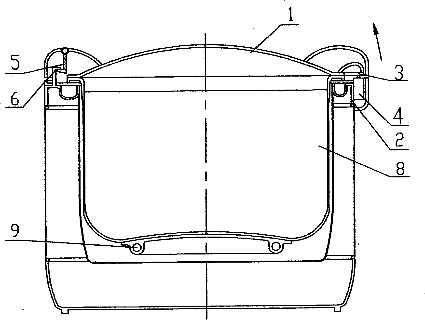
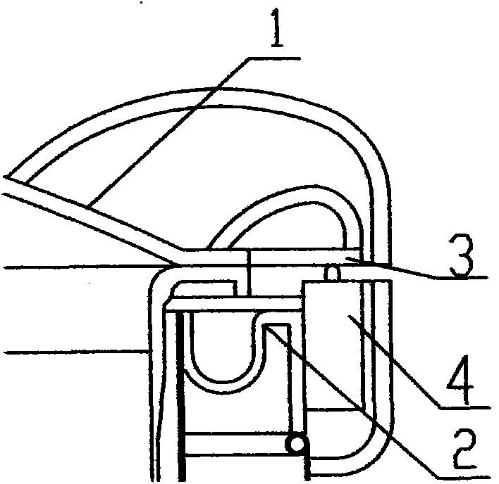
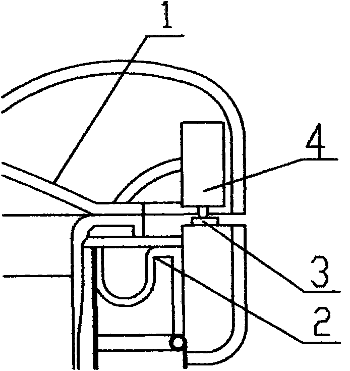
[0032] Embodiment 1: see attached figure 1 . On the side of the junction of the pot cover part 1 and the pot body part 2 ( figure 1 Right side in ), set the control mechanism. Such as figure 2 As shown, the transmission part 3 in the control mechanism is a rigid structural member, which is fixedly arranged on the pot cover part 1 or made into one with the pot cover part 1, so that it can move synchronously with the pot cover part 1. The switch 4 can be selected as a micro switch whose electrical parameters are about 200g·f on-off displacement force and about 0.1mm on-off displacement sensitivity. The switch 4 is arranged on the pot body part 2 below the transfer member 3 . The setting positions of the transmission part 3 and the switch 4 should satisfy: when the pot cover part 1 is fastened, the gravity of the pot cover part 1 touches the contact of the switch 4 through the transmission part 3, so that the switch 4 is in the open state. When the pot cover part 1 is drive...

Embodiment 2

[0036] Embodiment 2: see specification attached Figure 7 . The fulcrum mechanism is arranged on the side where the pot cover part 1 and the pot body part 2 join ( Figure 7 left). Wherein the fixing part 6 and the buckle insert 5 are combined by using a plug-in shaft structure. Such as Figure 8 As shown, the fixing member 6 is made into a shaft seat structure with holes, which is arranged on the pot body part 2 or made integral with the pot body part 2 . The buckle insert 5 is made into a structural part with a shaft, which is arranged on the pot cover part 1 or made into one with the pot cover part 1. The relevant dimensions of the shaft should match the relevant dimensions of the shaft hole on the fixture 6, so that the buckle insert 5 can be inserted into the shaft hole on the fixture 6. The junction of the shaft and the shaft hole can not only fix and support the pot cover part 1, but also make the pot cover part 1 take this as the fulcrum for opening and closing di...

Embodiment 3

[0038] Embodiment 3: see specification attached Figure 10 . In this embodiment, the connection between the pot cover part 1 and the pot body part 2 is based on the rotating shaft structure adopted by the existing one-piece electric rice cooker. The rotating shaft structure is composed of a shaft and a shaft seat with a shaft hole. The shaft seat is arranged on the pot cover part 1 and the pot body part 2, and the shaft is passed through the shaft hole on the shaft seat to connect the pot cover part 1 and the pot body part 2 as a whole. Simultaneously, the shaft and the pot cover part 1 should be rigidly connected so that the shaft can follow the pot cover part 1 to rotate synchronously. Set the control mechanism on the shaft structure (see Figure 11): The transmission member 3 is arranged on the shaft or integrated with the shaft, that is, the shaft is the transmission member 3 . The switch 4 is arranged on the pot body part 2 where the transmission part 3 can touch and ...


PUM


Abstract

The invention discloses a movable cover controlling device, belonging to the field of an electric heating cooking appliance used for a kitchen. The movable cover controlling device adopts a pressure control way and works within a normal pressure range. The movable cover controlling device comprises a pot cover part, a pot body part, an inner pot and an electric heating disc, wherein a control mechanism is arranged at one side of the connecting part between the pot cover part and the pot body part, and comprises a transmission piece and a switch; the transmission piece used for transmitting the displacement force or the gravity of the pot cover part is arranged correspondingly to the switch up and down; a supporting point mechanism is positioned at the other side of the connecting part between the pot cover part and the pot body part, and comprises a fixing piece and a buckling inserting piece which are respectively arranged on the pot cover part and the pot body part; and the fixing piece and the buckling inserting piece are combined with each other, so that the pot cover part can make opening and closing displacement by taking a combining point of the fixing piece and the buckling inserting piece as a supporting point. The movable cover controlling device solves the problems of high power consumption, single function, poor cooking effect and the like in the prior art, and has the advantages of being simple in structure, saving production cost, being low in probability of failure, and the like.

Description

Technical field: [0001] The invention belongs to the field of electric cooking utensils for kitchens, and relates to a movable cover control device which adopts a pressure control mode and works in a normal pressure range. Background technique: [0002] Existing electric heating cooking utensils can be divided into normal pressure type and pressure type. According to the relevant standards of our country, if the steam pressure in the pot is in the range of 4kPa ~ 140kPa (gauge pressure, the same below), it belongs to the pressure type, and if the steam pressure is below 4kPa, it is the normal pressure type. The difference in structural forms of these two prior art is mainly manifested in the presence or absence of pressure bearing structures and pressure safety precautions. [0003] In normal-pressure electric cooking appliances, the existing magnetic steel temperature-controlled rice cooker technology cannot control the phenomenon of porridge and soup overflowing during co...

Claims


Application Information

Patent Timeline
Patent Type & Authority Patents(China)
IPC IPC(8): A47J36/06A47J27/00
Inventor 王永光
Owner 王永光
Why Eureka
Try Eureka