Combined rotating baking tray

A combination and bakeware technology, applied in the direction of baking equipment, household utensils, applications, etc., can solve the problems of increased storage space for bakeware, difficult structure manufacturing, and failure of the entire structure, so as to facilitate mass production, Save space and beautify the appearance

Inactive Publication Date: 2012-11-28
宁波福凯电子科技有限公司
View PDF1 Cites 1 Cited by
  • Summary
  • Abstract
  • Description
  • Claims
  • Application Information

AI Technical Summary

Problems solved by technology

[0002] A rotatable baking pan structure, such as the Chinese patent "Rotating Baking Pan" (notification number CN201328717Y) whose patent number is ZL200820170991.8; The supporting seat and the second supporting seat, a concave cavity is arranged between the first supporting seat and the second supporting seat, and the concave cavity is embedded with the baking pan body; one side of the baking pan body is equipped with a temperature control base, and the baking pan body The other side is equipped with a handle base; the handle base is rotatably connected to the upper edge of the second support seat, and the temperature control base is rotatably connected to the upper edge of the first support seat; the support seat and the base are designed integrally, and its structure is difficult to manufacture Large and difficult to maintain, when a support seat or base is damaged, the entire structure will fail; the handle itself is an integral structure and cannot be moved, so the space for placing the entire baking pan will be greatly increased

Method used


Image

  • Combined rotating baking tray
  • Combined rotating baking tray
  • Combined rotating baking tray

Examples


Embodiment Construction

[0022] The present invention will be further described in detail below in conjunction with the accompanying drawings and embodiments.

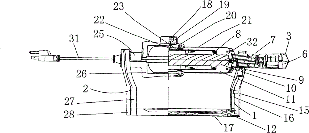
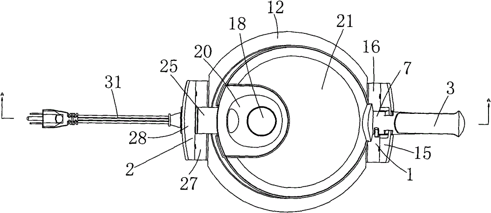
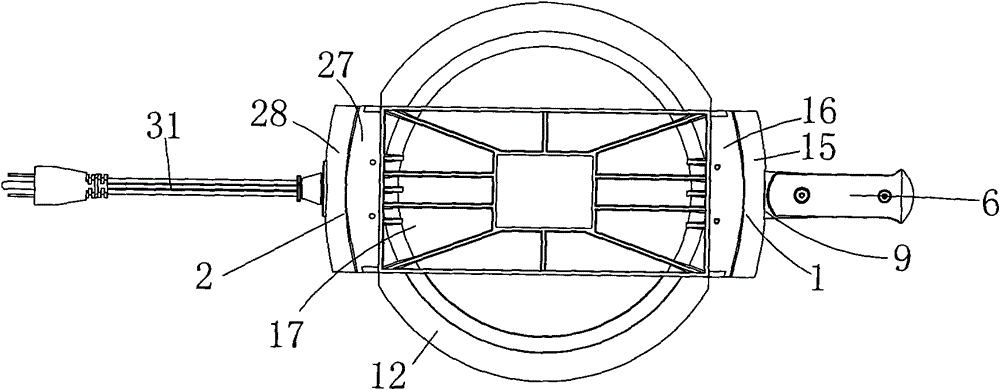
[0023] Such as Figure 1 to Figure 6 As shown, the icon numbers are explained as follows: right support body 1, left support body 2, upper handle 3, handle stopper 4, handle stopper slingshot 5, lower handle 6, rotation shaft 61, upper handle connector 7, rotation hole 71 , heating pipe 8, lower handle connector 9, lower heating plate 10, lower cover 11, debris tray 12, parallel straight sides 12a, handle fixing spring 13, handle fixing slingshot 14, right handle outer fixing plate 15, right Handle inner fixing plate 16, fixed connector 17, temperature control knob 18, temperature control bushing 19, upper temperature control seat 20, upper cover 21, temperature controller 22, mica heat shield 23, bushing 24, pressure wire Clip 25, lower temperature control seat 26, left handle inner fixed plate 27, left handle outer fixed plate 28, power cor...


PUM


Abstract

The invention discloses a combined rotating baking tray. The combined rotating baking tray comprises a fixed connecting piece, and an upper heating tray and a lower heating tray which are formed by clasping the surfaces, wherein the two ends of the fixed connecting pieces are provided with a left supporting body and a right supporting body respectively; the bottom surface of the lower heating tray is provided with a lower cover, and one end of the lower cover is provided with a lower handle connecting piece, and the other end of the lower cover is provided with a lower temperature control seat; the lower temperature control seat is in running fit with the upper end of the left supporting body, and the lower handle connecting piece is in running fit with the upper end of the right supporting body; the left and right supporting bodies adopt a two-part assembling structure, and are quick to assemble and dissemble, the structure is simplified, the whole appliance is assembled by parts, and the tray is favorable for batch production; an upper cover is mainly used for covering the top surface of the upper heating tray, has a simple structure and attractive appearance, and plays a role in protecting the upper heating tray at the same time; an upper part is provided with a handle to realize the arrangement and positioning of a lower handle skillfully, and has a reasonable structure; and a two-heating pipe structure can improve the making speed of baking tray food, so that the processing efficiency of the whole appliance is improved.

Description

technical field [0001] The invention relates to the technical field of electric heating appliances, in particular to a combined rotary grill. Background technique [0002] A rotatable baking pan structure, such as the Chinese patent "Rotating Baking Pan" (notification number CN201328717Y) whose patent number is ZL200820170991.8; The support seat and the second support seat are equipped with a concave cavity between the first support seat and the second support seat, and the concave cavity is embedded with the baking pan body; one side of the baking pan body is equipped with a temperature control base, The other side is equipped with a handle base; the handle base is rotatably connected to the upper edge of the second support seat, and the temperature control base is rotatably connected to the upper edge of the first support seat; the support seat and the base are designed integrally, and its structure is difficult to manufacture It is large and difficult to maintain. When a...

Claims


Application Information

Patent Timeline
Patent Type & Authority Patents(China)
IPC IPC(8): A47J37/04
Inventor 施军达张华平
Owner 宁波福凯电子科技有限公司
Why Eureka
Try Eureka