Power storage control apparatus and method of electric vehicle

A storage control and electric vehicle technology, applied in battery/fuel cell control devices, electric vehicles, DC motor traction, etc., can solve the problem of deteriorating stop position accuracy

Active Publication Date: 2010-10-20
KK TOSHIBA
View PDF7 Cites 16 Cited by
  • Summary
  • Abstract
  • Description
  • Claims
  • Application Information

AI Technical Summary

Problems solved by technology

[0006] In addition, in the train stop control of automatic train operation, the power absorption un

Method used


Image

  • Power storage control apparatus and method of electric vehicle
  • Power storage control apparatus and method of electric vehicle
  • Power storage control apparatus and method of electric vehicle

Examples


Embodiment Construction

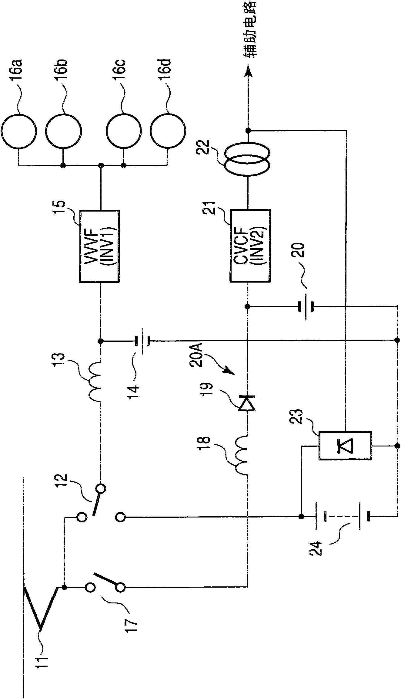
[0023] Embodiments of the present invention will now be specifically described. First refer to figure 1 The generalized circuit of the electric vehicle circuit shown in , is used to explain the driving control method currently used, for example, by trolleybuses capable of running on battery power.

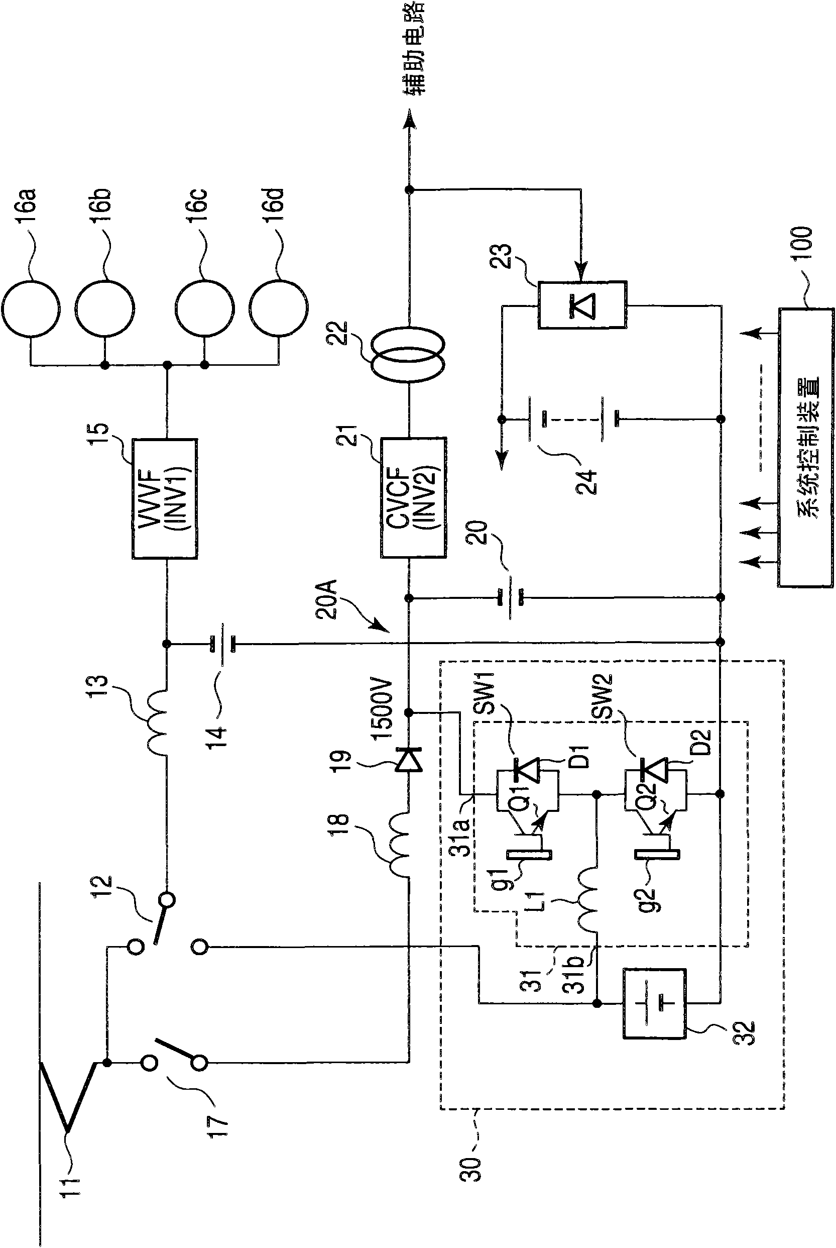
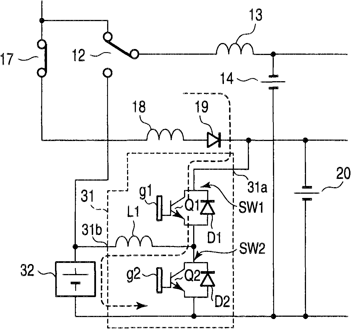
[0024] The current collector 11 , which collects power from the outside such as the electric vehicle line, supplies its output power to the contactors 12 and 17 . In a normal state, the power that has passed through the contactor 12 is filtered by the reactor 13 and the capacitor 14 and supplied to a variable voltage variable frequency (VVVF) inverter 15 . In a normal state, power that has passed through the contactor 17 is supplied to a constant voltage constant frequency (CVCF) inverter 21 via an input circuit 20A including a reactor 18 , a blocking diode 19 and a capacitor 20 . Reactor 18 and capacitor 20 form a filter.

[0025] The output from the VVVF inverter 15 is supplie...


PUM


Abstract

A power storage control apparatus of one embodiment of the present invention includes a step-up/step-down chopper (31), a contactor (12) and a control unit (100). The control unit (100) is configured to control the contactor (12) so as to make the contactor supply the voltage from the overhead wire to the input portion of the VVVF inverter (15) of the main circuit in a normal running state and supply the voltage of the power storage device to the input portion of the VVVF inverter (15) in the second running state, and control the step-up/step-down chopper so as to make the step-up/step-down chopper perform a step-down operation to charge the power storage device (32) in the first running state and perform a step-up operation to discharge the power storage device (32) and supply the power to the CVCF inverter (21) in an emergency running state.

Description

Background technique [0001] The invention relates to a power storage control device and method for an electric vehicle running on a railway. The power storage control device is effectively applicable to a control device that supplies power from a power storage device provided in an electric vehicle until it cannot receive power (for example, in the case of a power failure in an overhead line or when there is no overhead line The main circuit of the electric vehicle in the region), so that the electric vehicle can run at a low speed to the nearest power supply point. [0002] When power supply from an overhead line or the like is impossible, current electric vehicles cannot move and need to wait for a rescue vehicle. However, some trolleybuses have solved this problem, enabling them to use on-board batteries as a power source, for example, to move around garages without overhead lines. In trolleybuses, the load capacity of auxiliary circuits (lighting, air conditioning, etc.)...

Claims


Application Information

Patent Timeline
IPC IPC(8): B60L9/08
CPCB60L2200/26Y02T10/7044Y02T10/725B60L7/16B60L9/30B60L2210/12Y02T10/705B60L2210/20Y02T10/7233B60L11/1861Y02T10/7005B60L58/12Y02T10/70Y02T10/72
Inventor 古贺猛野木雅之户田伸一中泽洋介
Owner KK TOSHIBA
Why Eureka
Try Eureka