Static pressure and vibration composite test device for hydraulic tube and connecting joint thereof

A technology for connecting joints and compound tests, which is applied in fluid pressure actuation devices, fluid pressure actuation system tests, mechanical equipment, etc., can solve problems such as small amplitude, difficult data collection, and small selection of vibration waveforms, achieving simple structure, The effect of the test effect is obvious

Active Publication Date: 2010-10-20
中舟海洋科技(上海)有限公司
View PDF6 Cites 15 Cited by
  • Summary
  • Abstract
  • Description
  • Claims
  • Application Information

AI Technical Summary

Problems solved by technology

The existing vibration test device is to place the test piece on the vibrating table, apply pressure, and the whole test piece vibrates with the vibrating table. The disadvantages of the existing test device are: small vibration frequency range, small amplitude, difficult data acquisition and high accuracy. Not high, the vibration waveform selection is small, the main disadvantage is that it does not simulate the actual working conditions of the pipe connection

Method used


Image

  • Static pressure and vibration composite test device for hydraulic tube and connecting joint thereof
  • Static pressure and vibration composite test device for hydraulic tube and connecting joint thereof
  • Static pressure and vibration composite test device for hydraulic tube and connecting joint thereof

Examples


Embodiment Construction

[0031] The following combination figure 1 and figure 2 , to describe preferred embodiments of the present invention in detail.

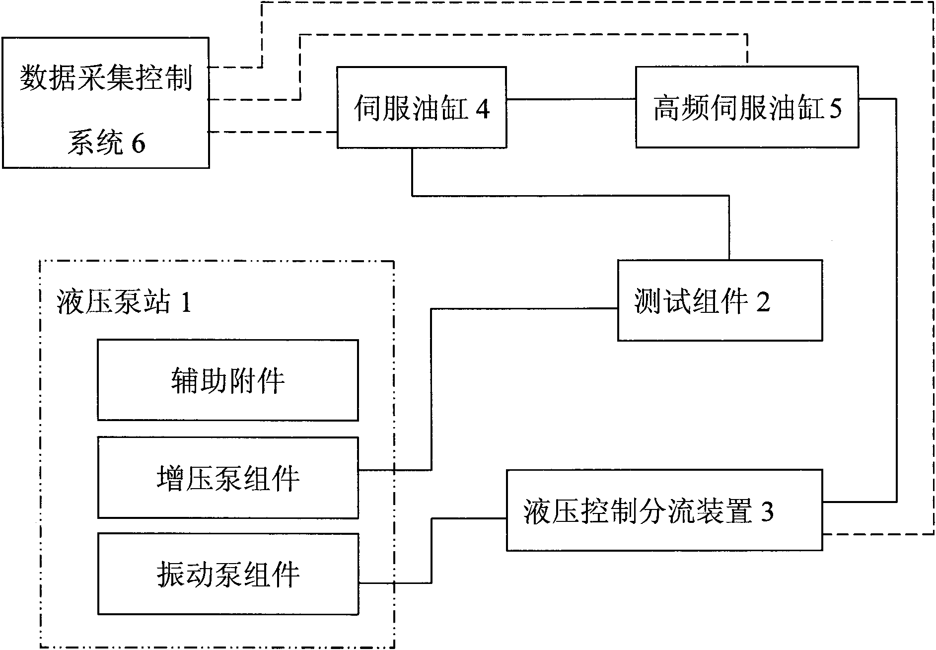
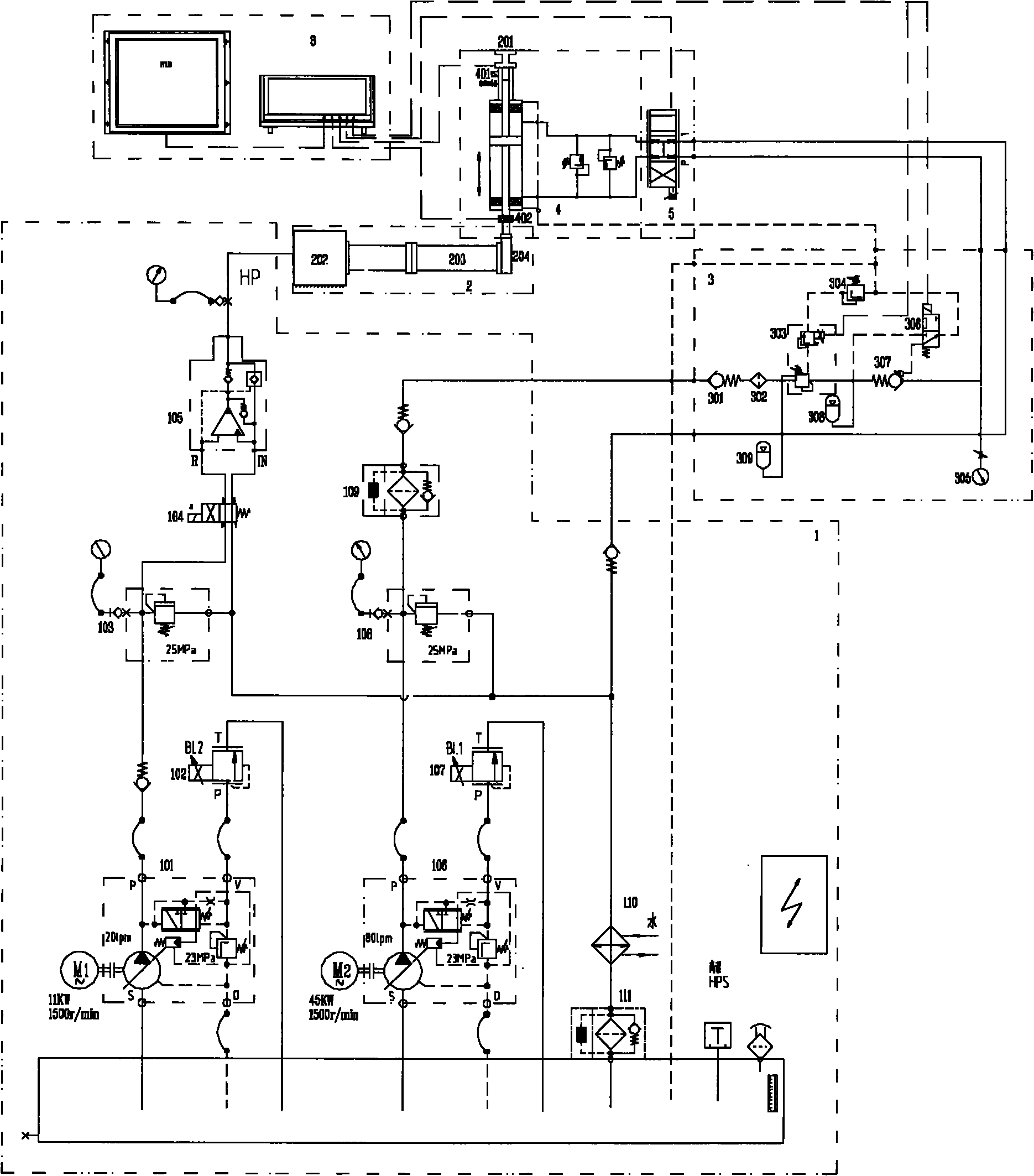
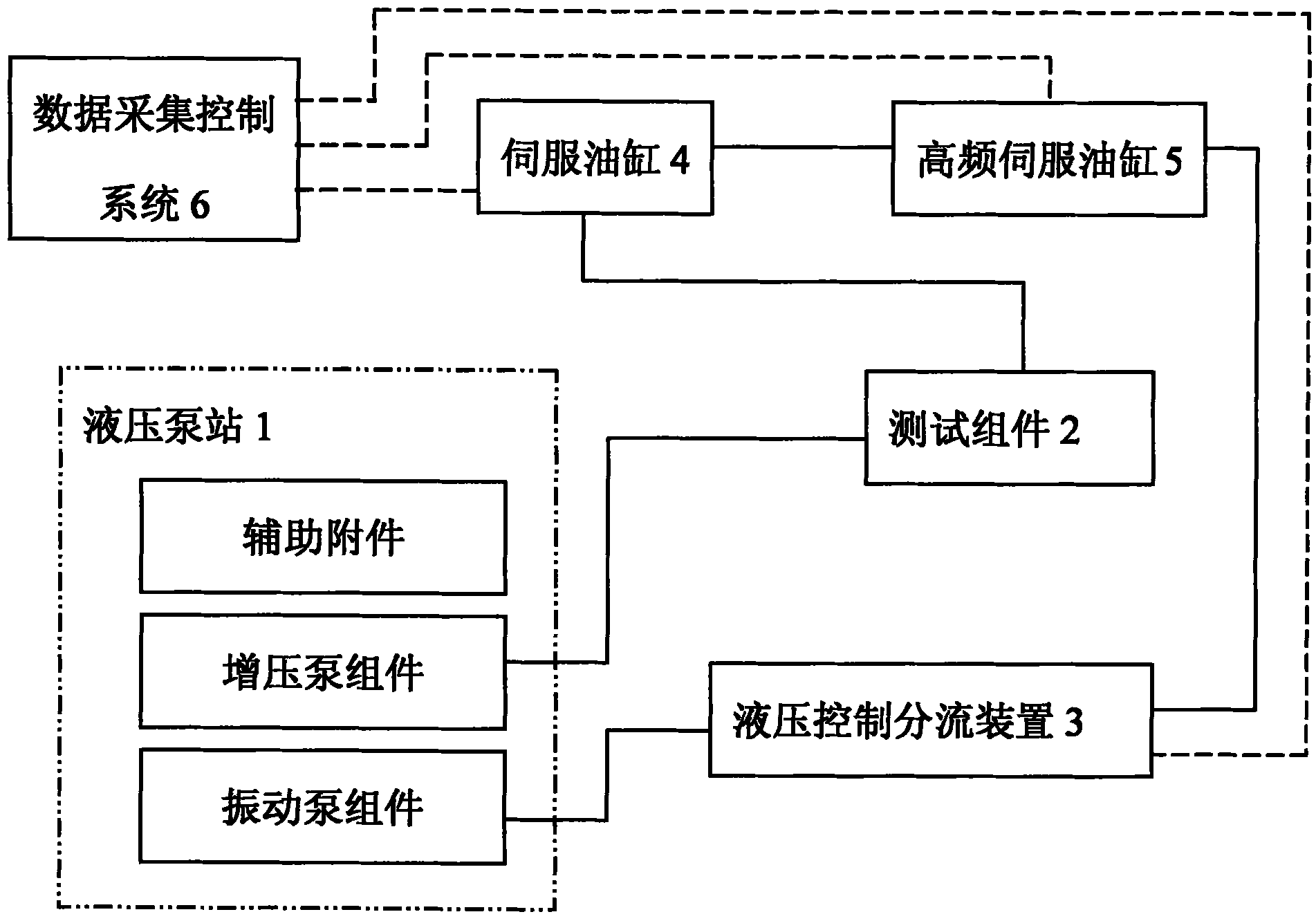
[0032] like figure 1 as shown, figure 1 It is a structural block diagram of the present invention. A static pressure and vibration composite test device for hydraulic pipes and their connecting joints, which is used to perform static pressure and deflection vibration composite tests on a test piece 203, including a hydraulic pump station 1, a test component 2, a hydraulic control shunt device 3, Servo oil cylinder 4, high frequency servo valve 5 and data acquisition control system 6. The hydraulic pump station 1 includes a pump assembly, a pressure regulating and boosting assembly and an auxiliary assembly, which are respectively connected to the test assembly 2 and the hydraulic control split device 3 through hydraulic hoses and pipe joints. The hydraulic control split device 3 is connected to the integrated high The servo cylinder 4 of the fr...


PUM


Abstract

The invention discloses a static pressure and vibration composite test device for a hydraulic tube and a connecting joint thereof. The device comprises a hydraulic pump station, a test assembly, a hydraulic control shunt device, a servo cylinder, a high-frequency servo valve and a data acquisition control system. The test assembly comprises a fixed valve block, a vibrating valve block and a test piece, wherein the test piece consists of the hydraulic tube and the connecting joint to be tested; one end of the test piece is connected with the fixed valve block while the other end is connected with one end of the vibrating valve block; the other end of the vibrating valve block is connected with a piston rod of the servo cylinder; the hydraulic pump station provides hydraulic supply; the hydraulic control shunt device is connected with the servo cylinder on which the high-frequency servo valve is integrated; the data acquisition control system is connected with a hydraulic shunt device, the servo cylinder and the high-frequency servo valve; the servo cylinder drives the vibrating valve block to move up and down reciprocally so as to realize the bending of the overall test piece; and the hydraulic pump station provides a static pressure for the test piece through the fixed valve block so as to perform a static pressure test and a vibration test on the test piece at the same time. The device has the characteristics of simple structure and obvious test effect.

Description

technical field [0001] The invention relates to a static pressure and vibration composite test device, in particular to a static pressure and vibration composite test device for a hydraulic pipe and its connecting joints. Background technique [0002] Hydraulic pipes and their connecting joints are prone to fatigue due to mechanical vibration under working conditions. In order to determine the ability of the hydraulic pipe and joint assembly to withstand fatigue, it is necessary to conduct a vibration test under static pressure conditions for the assembly. The existing vibration test device is to place the test piece on the vibrating table, apply pressure, and the whole test piece vibrates with the vibrating table. The disadvantages of the existing test device are: small vibration frequency range, small amplitude, difficult data acquisition and high accuracy. The vibration waveform is not high, and the vibration waveform selection is small. The main disadvantage is that it d...

Claims


Application Information

Patent Timeline
Patent Type & Authority Applications(China)
IPC IPC(8): F15B19/00
Inventor 周武黄作英
Owner 中舟海洋科技(上海)有限公司
Why Eureka
Try Eureka