Anti-cavitation erosion adjusting valve capable of cutting

A technology for regulating valves and anti-cavitation, which is applied in the direction of lifting valves, valve details, valve devices, etc., can solve the problems of unavoidable cavitation, cavitation cannot be prevented, and high cost, so as to eliminate cavitation and ensure sealing performance , The effect of simple internal structure

Inactive Publication Date: 2010-10-20
WUXI SMART AUTO CONTROL ENG CO LTD
View PDF7 Cites 14 Cited by
  • Summary
  • Abstract
  • Description
  • Claims
  • Application Information

AI Technical Summary

Problems solved by technology

[0004] In fact, method 1 is often difficult to avoid cavitation in the last stage, and the multi-stage step-down bending flow path processing is responsible, and the cost is high; method 2 The pressure release curve of the valve is the same as that of a general valve, and cavitation cannot be prevented. Just because the cage forms a space between the valve body and the valve core, the damage caused by the cavitation phenomenon does not directly contact the inside of the valve body, which greatly reduces the degree and effect of the damage

Method used


Image

  • Anti-cavitation erosion adjusting valve capable of cutting
  • Anti-cavitation erosion adjusting valve capable of cutting
  • Anti-cavitation erosion adjusting valve capable of cutting

Examples


Embodiment Construction

[0013] The present invention will be further described below in conjunction with drawings and embodiments.

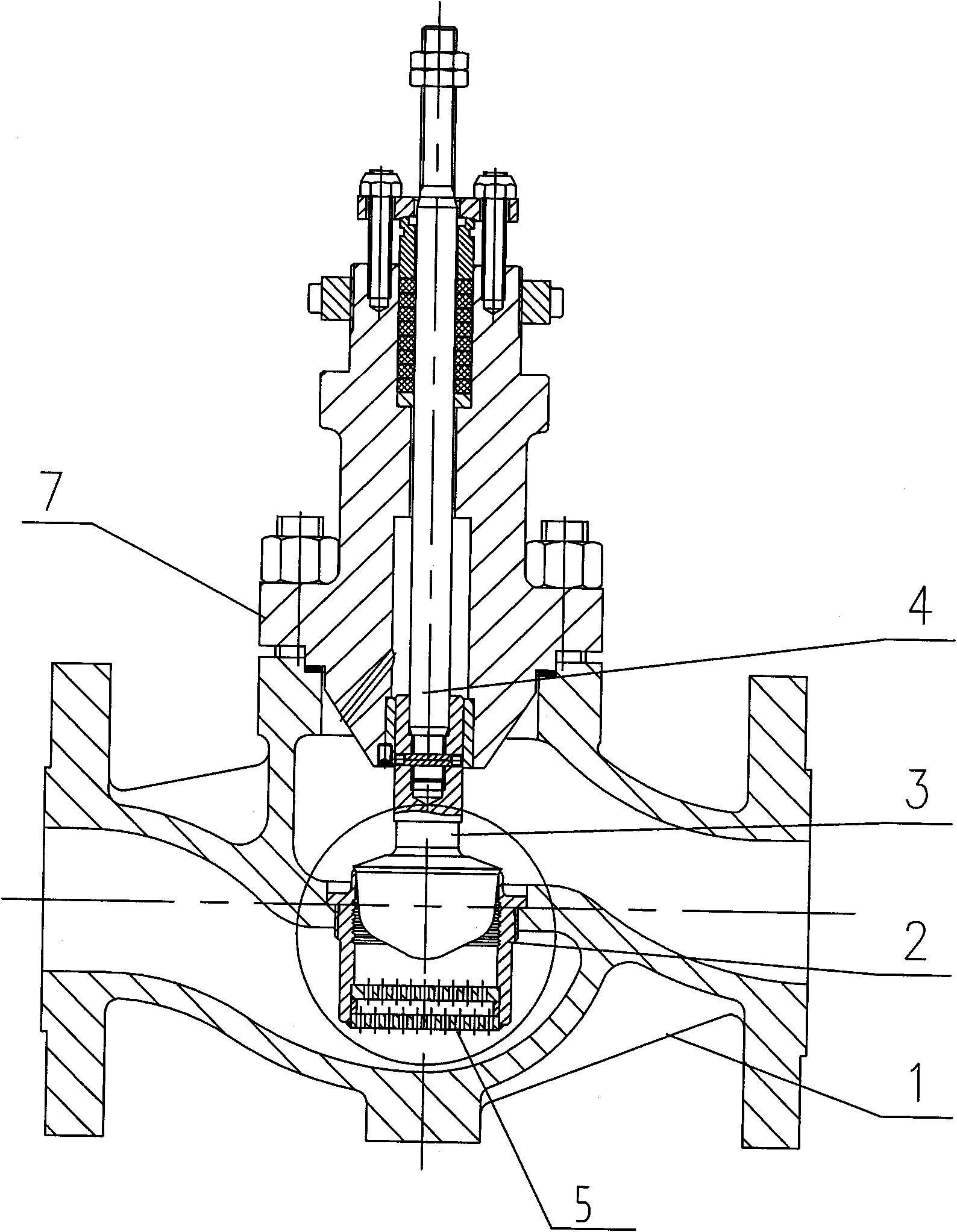
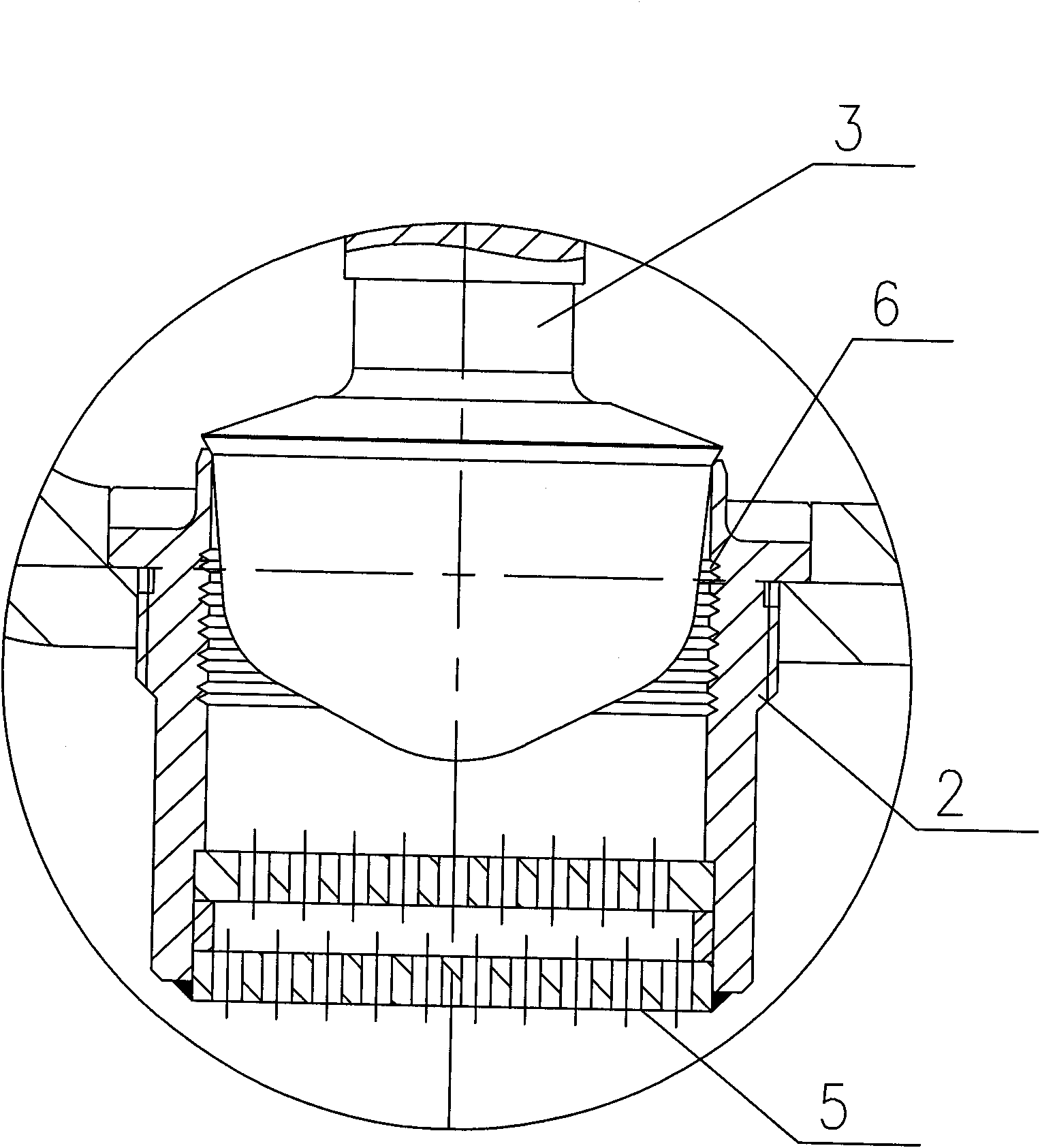
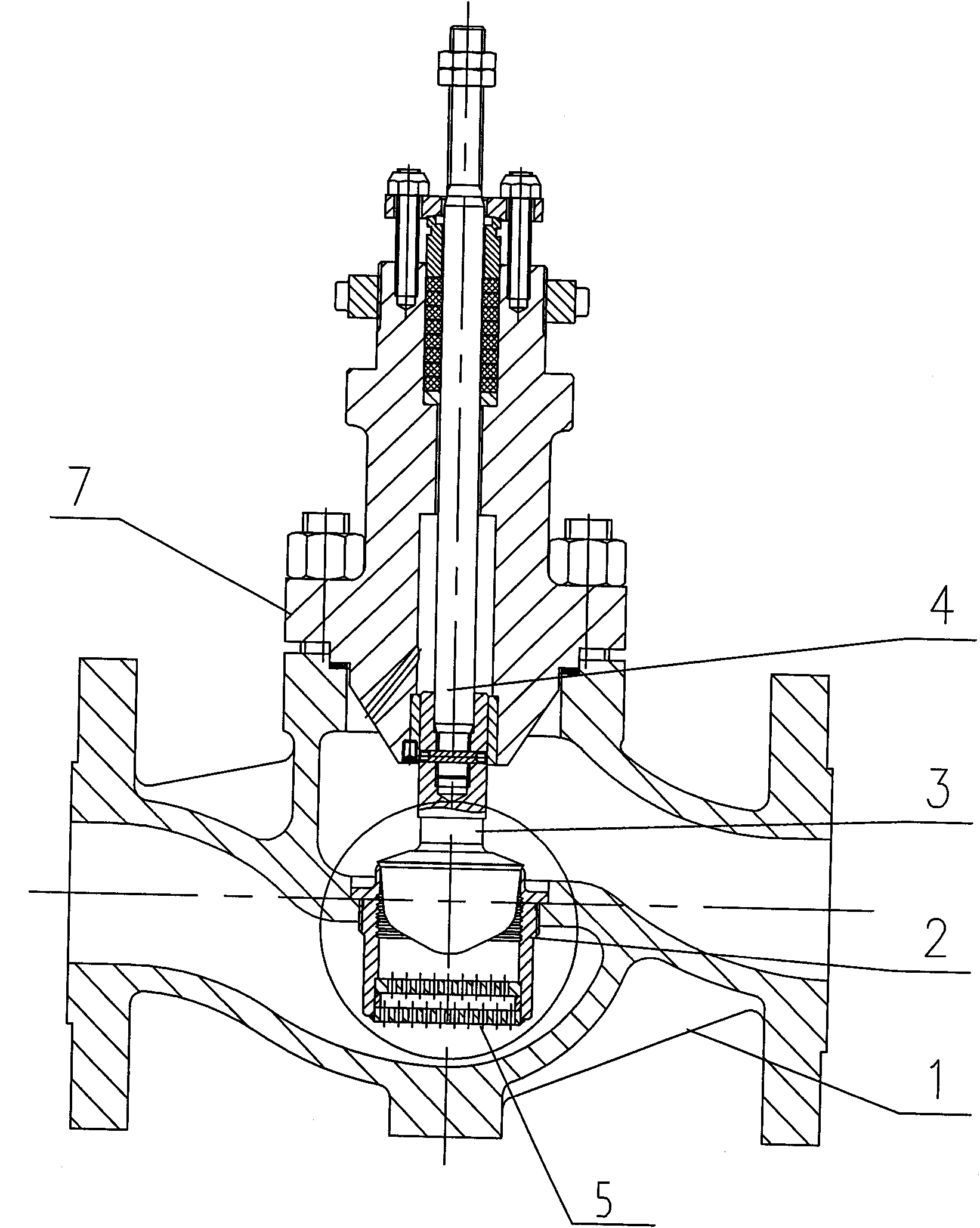
[0014] Such as figure 1 , 2 As shown, the present invention comprises valve body 1, valve seat 2, valve core 3 and valve stem 4, and valve seat 2 is screwed in the seat hole of valve body 1, and valve stem 4 is screwed in the valve stem hole of valve core 3 and valve core 3 fastening, the sealing surface of the valve seat 2 has a sharp cut, and the upper side of the valve core sealing surface of the valve core assembly 3 also has a sharp cut, the sealing surface of the valve core is in close contact with the sealing surface of the valve seat 2; the lower part of the valve seat 2 is set There are two or more layers of throttling orifice plates 5 parallel to each other, and the throttling orifice plates 5 are densely covered with small holes. The valve stem 4 and the valve core 3 are assembled in the upper cover 7 . The upper end of the valve stem is equipped with a pa...


PUM


Abstract

The invention relates to an anti-cavitation erosion adjusting valve capable of cutting, which comprises a valve body, a valve seat, a valve core and a valve rod. The invention is characterized in that the sealed face of the valve seat is provided with a cut, the upper side of the sealed face of the valve core is provided with the cut, the valve core sealed face tightly contacts with the valve seat sealed face and the lower part of the valve seat is provided with two or more than two layers of parallel restriction orifices which are provided with small holes. The inner wall at the lower part of the valve seat sealed face is provided with a zigzag groove so that a zigzag swirl chamber is formed between the valve seat and the valve core. The invention adopts the valve seat cutting technology and cuts air bubbles generated by flash evaporation through the sharp cut of the valve seat sealed face, consequently the cavitation erosion is avoided and the damage of the cavitation erosion on the interior components of the valve is eliminated thoroughly.

Description

technical field [0001] The invention relates to an anti-cavitation cutting regulating valve, in particular to an industrial anti-cavitation cutting regulating valve under the condition of high pressure difference. Background technique [0002] Due to the increasing diversification of industrial production, there are many harsh working conditions in the field of process control, and high differential pressure is one of them. Due to throttling, flashing and cavitation are prone to occur under high pressure differential conditions, resulting in severe erosion and cavitation of valve internals and adjacent pipeline inner walls, ultimately affecting the normal use of the valve and the stability of the device. [0003] At present, there are two main methods commonly used by regulating valves to overcome such working conditions. One is the multi-stage depressurization method, which divides the pressure drop generated by the fluid passing through the regulating valve into several st...

Claims


Application Information

Patent Timeline
Patent Type & Authority Applications(China)
IPC IPC(8): F16K1/34F16K47/08
Inventor 陈彦张程张志超
Owner WUXI SMART AUTO CONTROL ENG CO LTD
Why Eureka
Try Eureka