
Boundary scanning test system and test method

A technology of boundary scan testing and testing equipment, applied in the direction of measuring electricity, measuring devices, measuring electrical variables, etc., can solve the problems of slow test speed, cost, and inability to test multiple printed circuit boards, so as to save test time and improve test performance. efficiency effect

Inactive Publication Date: 2010-10-20
HONG FU JIN PRECISION IND (SHENZHEN) CO LTD +1
View PDF4 Cites 15 Cited by
  • Summary
  • Abstract
  • Description
  • Claims
  • Application Information

AI Technical Summary

Problems solved by technology

[0003] However, most of the general boundary scan test systems are connected to the printed circuit board to send and receive data through the parallel interface of the computer or the PCI (Peripheral Component Interconnect, Peripheral Component Interconnect Standard) interface, which makes the test speed slower.
On the other hand, the current test system often only has one test bus, which can only connect a single printed circuit board for testing at a time, and cannot test multiple printed circuit boards at the same time. When testing multiple printed circuit boards, it will cost more test time or need to purchase more test equipment

Method used


Image

  • Boundary scanning test system and test method
  • Boundary scanning test system and test method
  • Boundary scanning test system and test method

Examples


Embodiment Construction

[0015] Please refer to figure 1 , the boundary-scan test system 10 of the present invention is used for testing whether some devices under test 112 are qualified, and its preferred embodiment comprises a test device such as a computer 100, a peripheral interface such as a USB interface 102, a microprocessor 104, a gate A circuit 106 , several I / O (Input / Output, input / output) drive interfaces 108 and several JTAG bus interfaces 110 . The device under test 112 is a printed circuit board supporting JTAG technology. The gating circuit 106 may include one or more gating chips to realize the multi-channel gating function, and the specific number can be set according to the actual number of devices under test 112 to be tested.

[0016] The computer 100 is connected to the microprocessor 104 through the USB interface 102, and the microprocessor 104 is also connected to the several I / O drive interfaces 108 through the gate circuit 106. 104 is also connected to the plurality of I / O dr...


PUM


Abstract

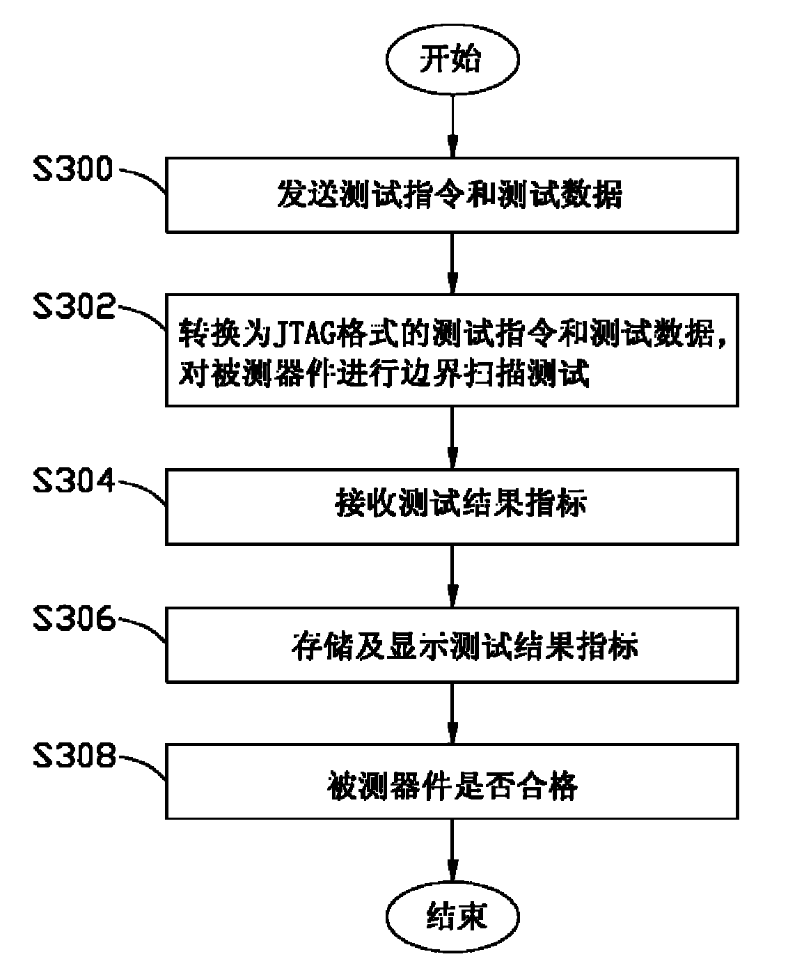
The invention discloses a boundary scanning test system, which comprises test equipment, an external interface, a microprocessor, a gating circuit, a plurality of I / O (Input / Output) driving interfaces and a plurality of JTAG (Joint Test Action Group) bus interfaces used for connecting devices to be tested. The test equipment is connected with the microprocessor through the external interface, the microprocessor is connected with the plurality of I / O driving interfaces through the gating circuit, each I / O driving interface is correspondingly connected with one JTAG bus interface, and the microprocessor is connected with the plurality of I / O driving interfaces. The invention also provides a boundary scanning test method. The boundary scanning test system and the boundary scanning test method can simultaneously test a plurality of devices to be tested so as to improve the test efficiency.

Description

technical field [0001] The invention relates to the field of electronic equipment testing, in particular to a testing system and a testing method for testing printed circuit boards through JTAG (Joint Test Action Group) technology. Background technique [0002] At present, in the field of integrated circuit testing of electronic equipment, it is often necessary to test the hardware of the printed circuit board to determine whether the chips on the printed circuit board are qualified, damaged or have processing failures such as short circuits or virtual soldering. Boundary scan testing is an important means of testing integrated circuits. It generally uses JTAG technology to test chips on printed circuit boards. The basic principle is to test internal nodes, Devices, etc. are tested. [0003] However, the general boundary-scan test system is mostly connected to the printed circuit board through a parallel interface of a computer or a PCI (Peripheral Component Interconnect, P...

Claims


Application Information

Patent Timeline
IPC IPC(8): G01R31/3185
Inventor 朱鸿儒
Owner HONG FU JIN PRECISION IND (SHENZHEN) CO LTD
Learn More