DC circuit breaker for improving arc blowout effect

A DC circuit breaker and arc extinguishing technology, which is applied in the electrical field, can solve problems such as the limited arc extinguishing effect of the arc extinguisher, and achieve the effects of prolonging life, reducing energy, and reducing damage

Inactive Publication Date: 2010-10-20
SHANGHAI LIANGXIN ELECTRICAL
View PDF3 Cites 6 Cited by
  • Summary
  • Abstract
  • Description
  • Claims
  • Application Information

AI Technical Summary

Problems solved by technology

However, the arc extinguishing effect of the arc extinguisher is limited

Method used


Image

  • DC circuit breaker for improving arc blowout effect
  • DC circuit breaker for improving arc blowout effect
  • DC circuit breaker for improving arc blowout effect

Examples


Embodiment 1

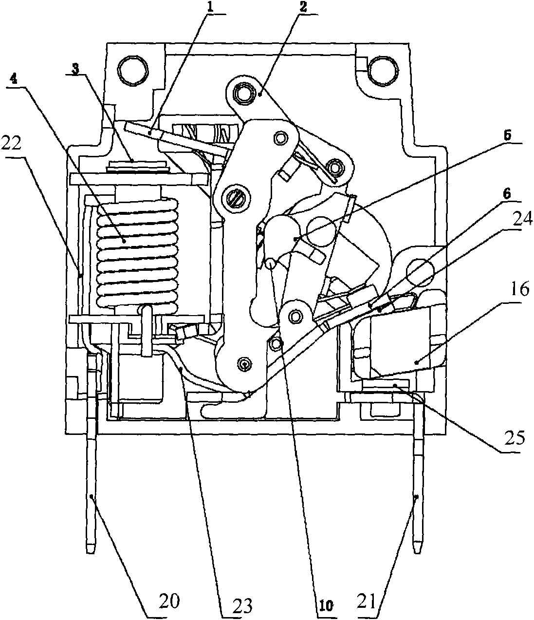
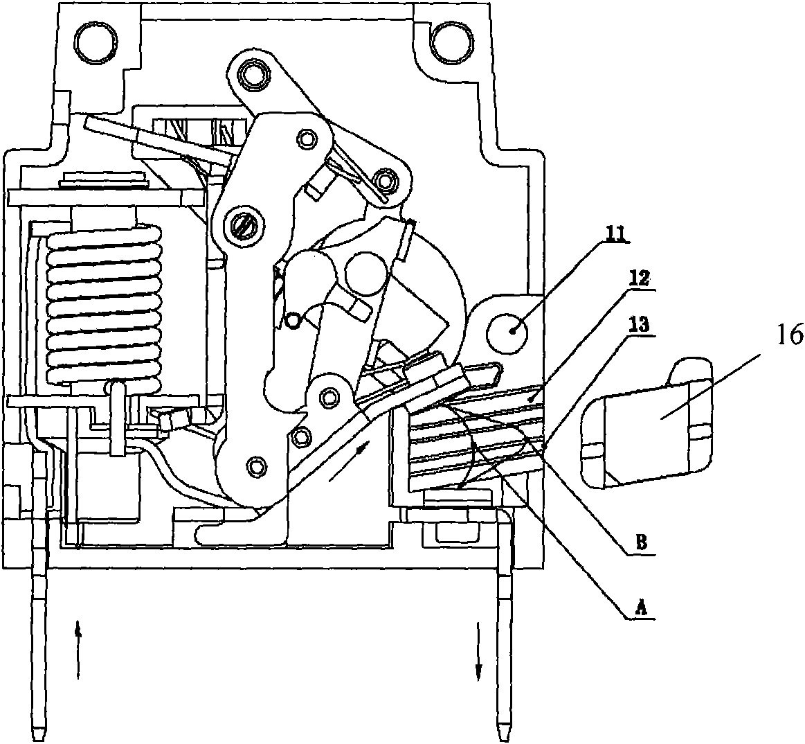
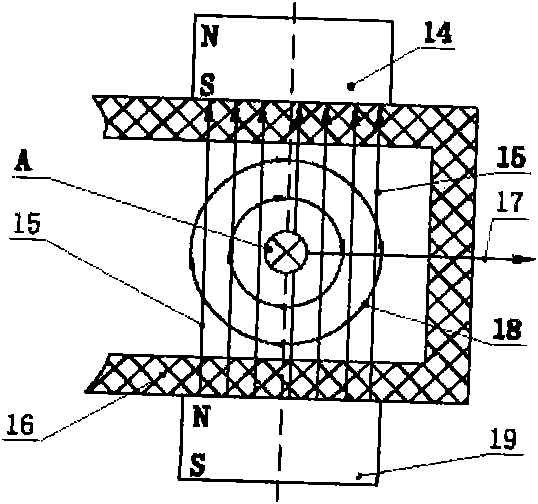
[0019] Such as figure 1 , figure 2 , image 3 and Figure 4 As shown, a DC circuit breaker with improved arc extinguishing effect of the present invention is composed of an electromagnetic circuit breaker, a permanent magnet 14 and a permanent magnet 19. The electromagnetic circuit breaker includes an insulating case 11, a first Connection terminal 20, second connection terminal 21, electromagnetic coil 4, delay tube, iron core, bracket, coil bobbin, armature 1, lock 10, movable contact arm 6, operator 2 and positioning member 5, the first A connecting terminal 20, a second connecting terminal 21, an electromagnetic coil 4, a delay tube 3, an iron core, a bracket, a coil bobbin, an armature 1, a lock 10, a movable contact arm 6, an operator 2 and a positioning member 5 are all arranged on In the insulating housing 11, the electromagnetic coil 4 is arranged on the bobbin, the bobbin is arranged around the delay tube 3, the iron core is arranged in the delay tube 3, the brac...


PUM


Abstract

The invention relates to a DC circuit breaker for improving the arc blowout effect, which is formed by an electromagnetic-type circuit breaker and two permanent magnets, wherein the electromagnetic-type circuit comprises an insulation shell and a movable contact, the two permanent magnets are respectively arranged on the insulation shell at two side of the route of the movable contact, and the direction of the magnetic pole of the two permanent magnets is identical to each other. The interior of an arc blowout chamber of the electromagnetic-type circuit breaker provides no arc blowout plate so when the movable contact and the static contact are opened to produce the electric arc, the magnetic field between the two permanent magnets is utilized to ensure that the electric arc current is transferred away from the contact, the deflected electric arc and the lengthened electric arc route increase the voltage drop of the electric arc and reduces the energy of the electric arc, and the loss of the movable and the static contacts is reduced, and the service life of the circuit breaker is prolonged.

Description

Technical field: [0001] The invention relates to the electrical field, in particular to a circuit breaker, in particular to a DC circuit breaker with improved arc extinguishing effect. Background technique: [0002] In the prior art, electromagnetic circuit breakers are widely used in power supply systems such as communication fields. The mechanism and terminals of the magnetic circuit breaker are housed in a pair of insulating plastic housings. Among them, there is an electromagnetic coil in the hydraulic electromagnetic circuit breaker that can pass the load current and voltage. The electromagnetic coil is wound around a delay tube, and there is an iron core in the delay tube. The pole shoe suction movement at the end of the delay tube. The bracket is used to support the coil bobbin and the surrounding coil, as well as a movable armature. The armature opens the electrical contacts by contacting a catch. When the electromagnetic circuit breaker is working, whether it is...

Claims


Application Information

Patent Timeline
Patent Type & Authority Applications(China)
IPC IPC(8): H01H73/18H01H9/44H01H71/24
Inventor 雒海珊丁飞
Owner SHANGHAI LIANGXIN ELECTRICAL
Why Eureka
Try Eureka