Removal of residual concrete from ready mixed concrete drums

A technology for ready-mixed concrete and mixing tanks, applied in cement mixing devices, clay preparation devices, cleaning methods using liquids, etc., can solve problems such as low efficiency, and achieve the effect of saving resources

Active Publication Date: 2010-10-20
BLASTERS
View PDF4 Cites 5 Cited by
  • Summary
  • Abstract
  • Description
  • Claims
  • Application Information

AI Technical Summary

Problems solved by technology

[0014] Instead of finding a way to position the nozzles close to the residual concrete during the cleaning process, the prior art has always positioned the nozzles along th

Method used


Image

  • Removal of residual concrete from ready mixed concrete drums
  • Removal of residual concrete from ready mixed concrete drums
  • Removal of residual concrete from ready mixed concrete drums

Examples


Embodiment Construction

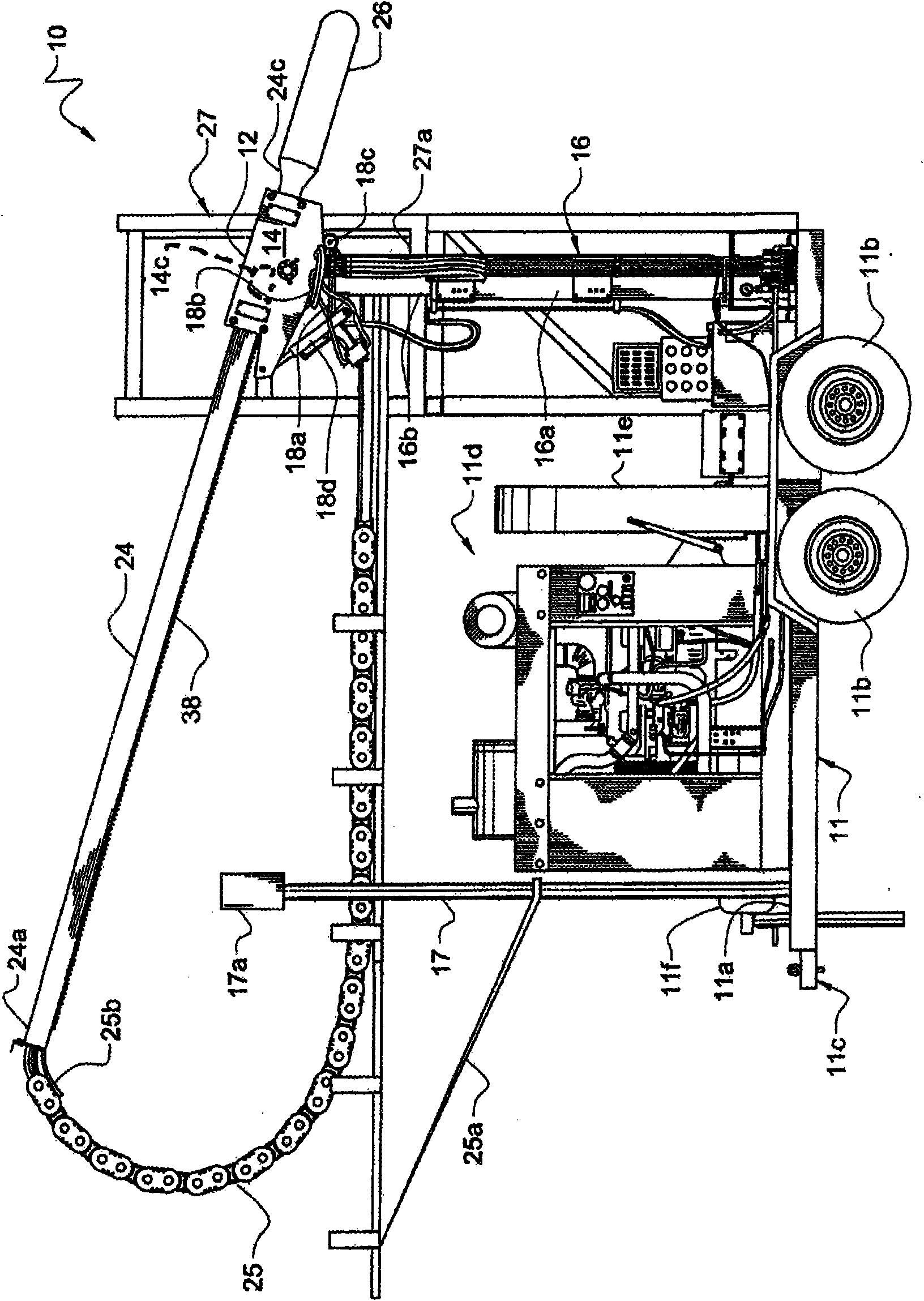
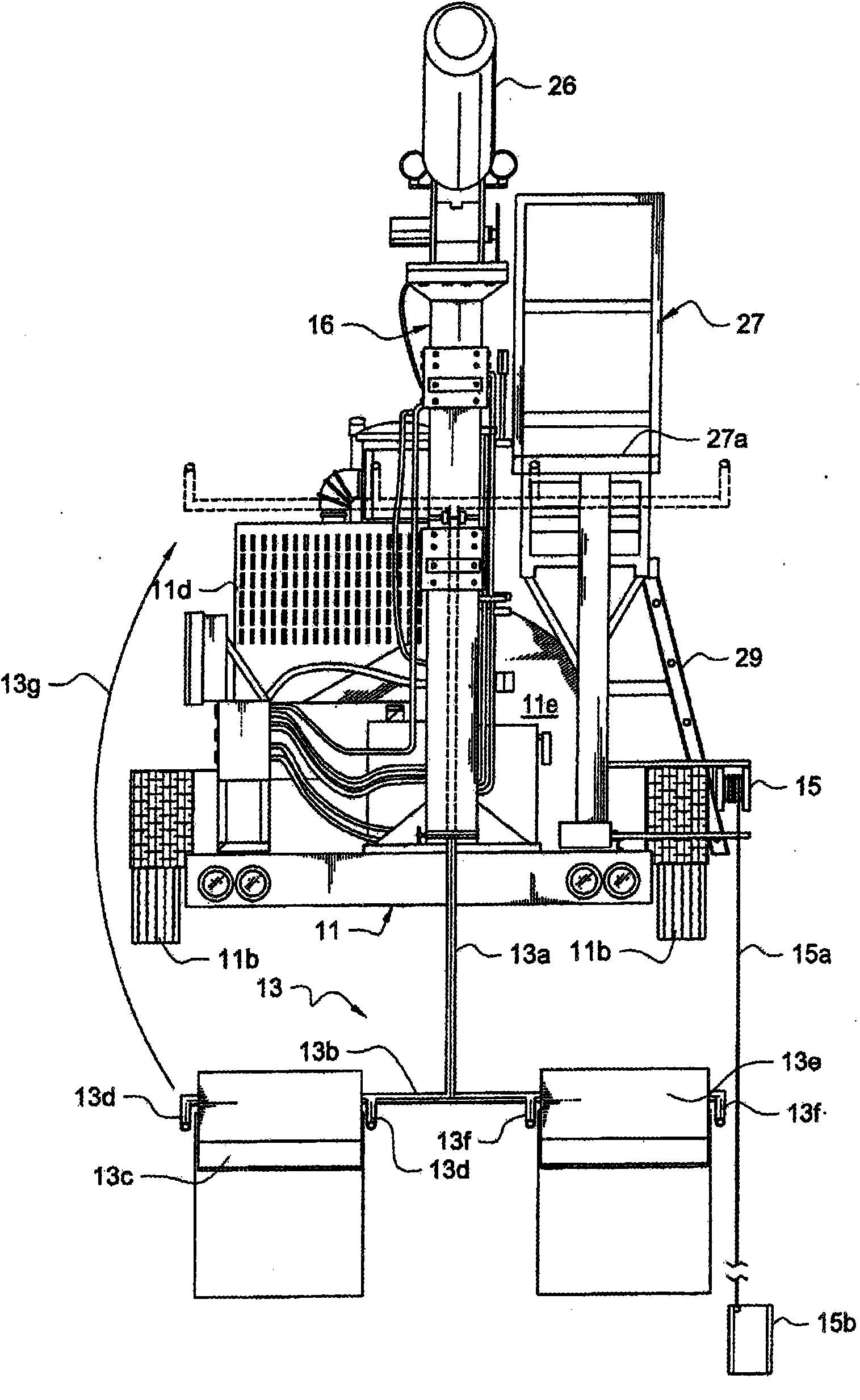
[0065] now refer to Figure 1A , it will be seen that an exemplary embodiment of the invention is indicated generally by the reference numeral 10 . Figure 1A Shown is a trailer 11 having a trailer bed 11a, wheels 11b, hitch assembly 11c, diesel engine 11d, pump belt guard 11e and diesel driven booster water pump 11f.

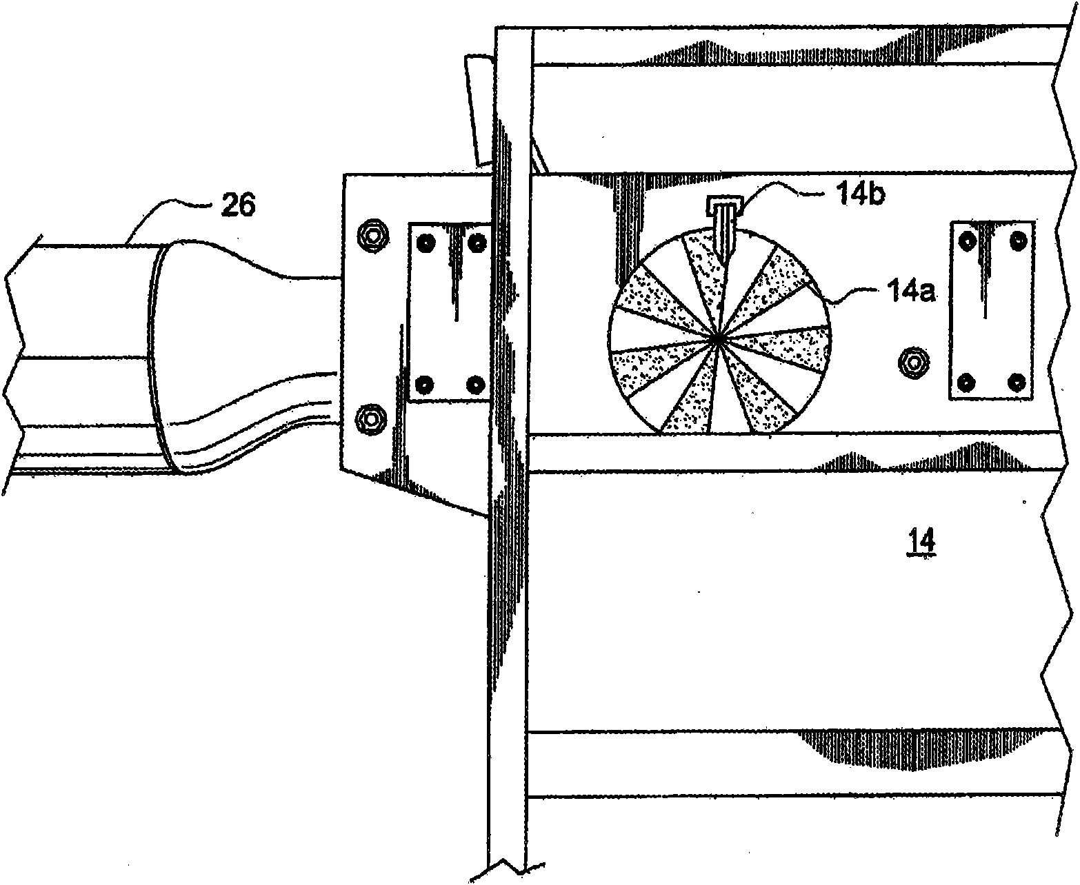
[0066] The hollow housing 12 is mounted atop a hydraulic motor mounting assembly 14 and said hydraulic motor mounting assembly 14 is arranged in a taller relationship than the tower 16 . The tower 16 includes a lower tube 16a that telescopically receives a movable upper tube 16b therein such that the height of the tower 16 is adjustable. This telescoping movement is preferably controlled by internal hydraulic cylinders, not shown.

[0067] The hinge assembly is mounted on the upper tower 16b. The top plate 18a is mounted on the upper tower 16b, and the support plate 18b is hingedly fixed to the top plate 18a by a hinge 18c. The hydraulic motor mounting assemb...


PUM


Abstract

Residual concrete in the drum of a ready mixed concrete truck is removed by high-pressure water. A nozzle is mounted on the leading end of a torpedo-shaped nozzle housing that is hingedly mounted to an elongate boom. The boom enters the mouth of the drum at an angle that matches the angle of the drum. The hinge allows the nozzle housing to pivot with respect to the elongate boom so that the nozzle is close to the residual concrete. The boom is retracted toward the mouth with the drum rotating in the mix direction and the nozzle oscillating so that it cuts through a swath of concrete. As the boom retracts, the torpedo-shaped nozzle housing maintains the nozzle close to the residual concrete on the drum and both sides of the helical fins. The nozzle sweeps an arc from about eighty to one hundred twenty degrees as it oscillates.

Description

[0001] Cross References to Related Publications [0002] This disclosure is a continuation-in-part of US Patent Application No. 11 / 535790 filed September 27, 2006 by the same inventor, which was filed September 30, 2005 by the same inventor A continuation-in-part of US Patent Application No. 11 / 240117 filed with the same inventive title as this disclosure. technical field [0003] The present invention generally relates to a method for removing concrete from the interior of a ready-mix concrete truck mixing tank. More specifically, the present invention relates to methods that do not require workers to enter the mixing tank, thereby protecting workers from various occupational hazards. Background technique [0004] The ready-mixed concrete mixing tank is rotatably mounted on the concrete truck so that when the concrete is transported from the concrete batching plant to the construction site, the concrete in the mixing tank can be continuously mixed, usually with the mixing ...

Claims


Application Information

Patent Timeline
IPC IPC(8): B08B9/04B08B3/00B08B3/04B08B9/00B08B3/12
CPCB08B3/02B28C5/4203B08B9/093
Inventor 弗雷德里克·A·布斯斯科特·F·布斯
Owner BLASTERS
Why Eureka
Try Eureka