Multi-modal spot generator and multi-modal multi-spot scanning microscope

A scanning microscope, generator technology, applied in microscopes, optics, lenses, etc., can solve problems such as switching troubles

Inactive Publication Date: 2010-10-20
KONINKLIJKE PHILIPS ELECTRONICS NV
View PDF2 Cites 28 Cited by
  • Summary
  • Abstract
  • Description
  • Claims
  • Application Information

AI Technical Summary

Problems solved by technology

However, switching between different imaging modes is often cumbersome as it requires physical changes to the microscope setup, such as exchanging the spot generator or mechanically readjusting the imaging optics

Method used


Image

  • Multi-modal spot generator and multi-modal multi-spot scanning microscope
  • Multi-modal spot generator and multi-modal multi-spot scanning microscope
  • Multi-modal spot generator and multi-modal multi-spot scanning microscope

Examples


Embodiment Construction

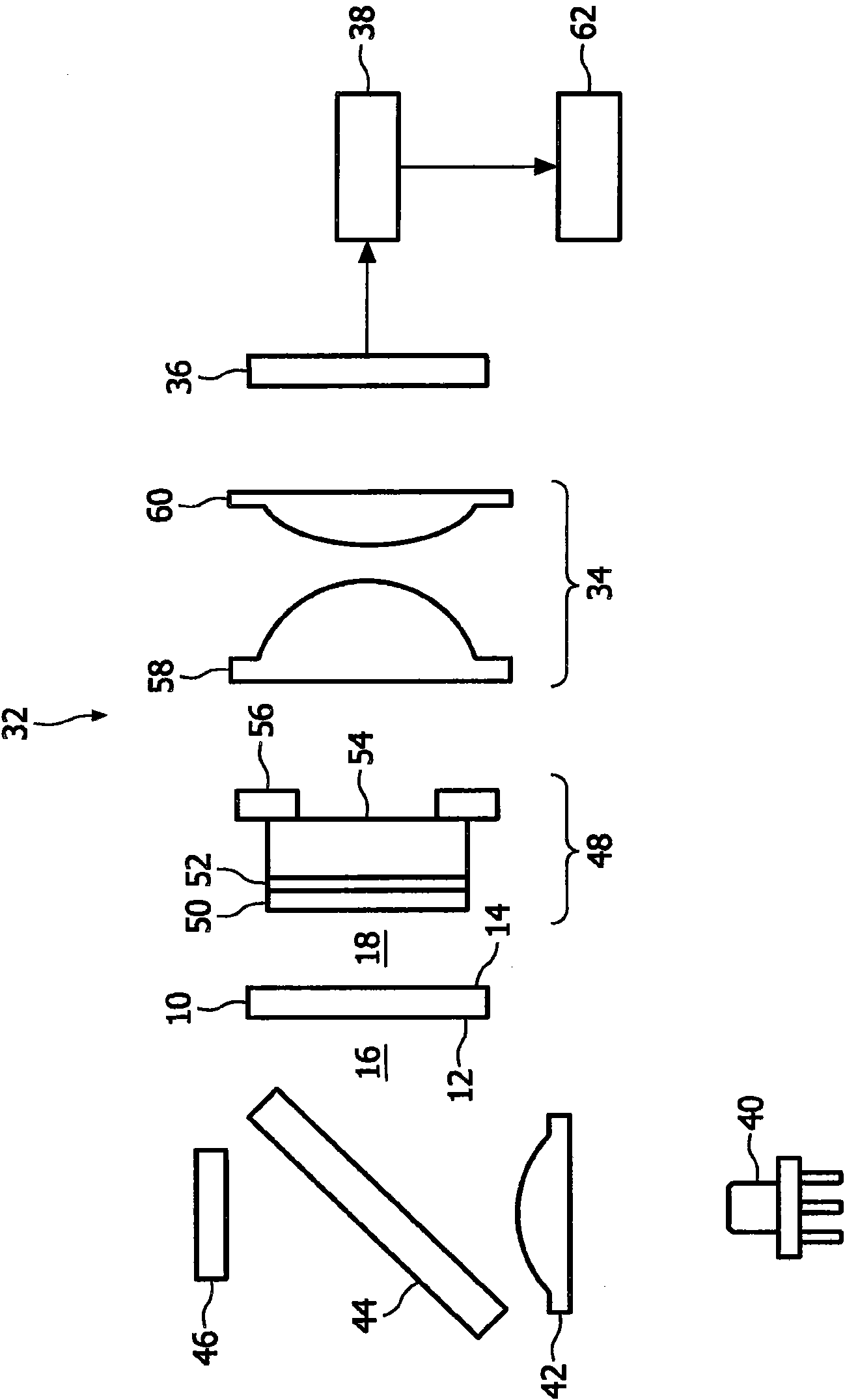
[0052] figure 1 Schematic illustrating the general architecture of a general-purpose multi-spot scanning microscope. The microscope includes laser 40, collimator lens 42, beam splitter 44, forward sensing photodetector 46, spot generator 10, sample assembly 48, imaging optics 34, pixelated photodetector 36, video processing integrated An electronic circuit (IC) 38 and a personal computer (PC) 62 . The spot generator 10 has an entry surface 12 defining an entry side 16 and an exit surface 14 defining an exit side 18 . Sample assembly 48 includes cover slide 50 , sample layer 52 , microscope slide 54 , and scanning stage 56 . Cover slide 50 , sample layer 52 and microscope slide 54 are placed on scanning stage 56 . Laser 40 emits a coherent beam that is collimated by collimator lens 42 and split by beam splitter 44 into a transmitted portion and a reflected portion. The transmitted portion of the light is picked up by forward sensing photodetector 46 to measure the light out...


PUM


Abstract

The invention relates to a spot generator (10) having: -an entrysurface (12) for receiving an incident light beam (20) and an exit surface (14) for transmitting the light beam, the entry surface defining an entryside (16) and the exit surface defining an exit side (18). According to the invention, the spot generator is designed to modulate the incident light beam to generate on the exit side a first plurality (22) and a second plurality (24) of separate light spots, each light spot belonging to the first plurality having a first angular spectrum and each light spot belonging to the second plurality having a second angular spectrum different than the first angular spectrum. Advantageously, the spot generator comprises a periodic binary phase structure. The invention further relates to a multi-spot scanning microscope and to a method of imaging a microscopic sample.

Description

technical field [0001] The present invention relates to a spot generator, which has: [0002] - an entry surface for receiving the incident beam, and [0003] - the exit surface for transmitting the beam, [0004] The entry surface defines an entry side and the exit surface defines an exit side. [0005] The invention also relates to multi-spot scanning microscopes and methods for imaging samples, especially microscopic samples. Background technique [0006] Optical multi-spot scanning microscopes are used to generate images of eg microscopic samples. These images are constructed by scanning the sample with an array of microscopic spots generated by the microscope's spot generator and by imaging the spots onto a detector, usually a photodetector. This microscope is suitable for the field of life sciences, especially the observation and research of biological specimens, digital pathology (that is, pathology using digitized images of microsections), automatic imaging-based...

Claims


Application Information

Patent Timeline
Patent Type & Authority Applications(China)
IPC IPC(8): G02B3/00G02B5/18G02B27/00G02B21/00G02B27/09
CPCG02B21/0032G02B27/0905G02B27/0087
Inventor S·斯托林加D·L·J·福森L·P·巴克B·胡什肯
Owner KONINKLIJKE PHILIPS ELECTRONICS NV
Why Eureka
Try Eureka