Dry method single-pressure recovery generating system of waste heat for cement production line

A dry process cement and power generation system technology, applied in waste heat treatment, machine/engine, lighting and heating equipment, etc., can solve the problem of low power generation efficiency, achieve the effect of improving steam quality, increasing effective enthalpy drop, and promoting efficiency

Inactive Publication Date: 2012-02-01
CHENGDU HOT NEW ENERGY TECH
View PDF0 Cites 0 Cited by
  • Summary
  • Abstract
  • Description
  • Claims
  • Application Information

AI Technical Summary

Problems solved by technology

[0004] In order to overcome the low power generation efficiency of the existing dry-process cement production waste heat recovery power generation system, the technical problem to be solved by the present invention is to provide a waste heat single-pressure recovery power generation system for a dry-process cement production line that can improve power generation efficiency

Method used


Image

  • Dry method single-pressure recovery generating system of waste heat for cement production line
  • Dry method single-pressure recovery generating system of waste heat for cement production line
  • Dry method single-pressure recovery generating system of waste heat for cement production line

Examples


Embodiment 1

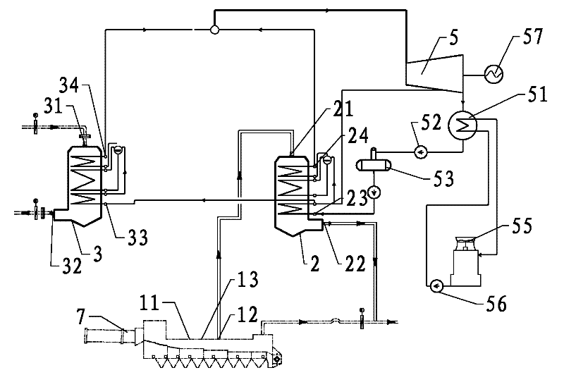
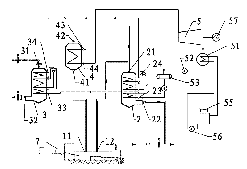
[0023] Such as image 3 As shown, the waste heat single-pressure recovery power generation system of the dry process cement production line of the present invention, the flue gas from the kiln tail C1 enters the kiln tail SP boiler 3 through the air inlet 31 to the raw material system after heat exchange, and the kiln head grate cooler 1 There are two gas inlets on the top, which are high temperature gas inlet 11 and medium temperature gas inlet 12. A high temperature superheater 4 is installed in the system. The flue gas from the high temperature gas inlet 11 enters the high temperature superheater 4 through the air inlet 41. After heat exchange The flue gas from the medium-temperature gas inlet 12 enters the dust removal system after heat exchange with the AQC boiler 2 through the air inlet 21, and the primary superheated steam from the steam outlet 24 of the AQC boiler 2 and the steam outlet 34 of the SP boiler 3 at the kiln tail is at high temperature After secondary super...

Embodiment 2

[0026] Such as Figure 4 As shown, the waste heat single-pressure recovery power generation system of the dry process cement production line of the present invention, the flue gas from the kiln tail C1 enters the kiln tail SP boiler 3 through the air inlet 31 to the raw material system after heat exchange, and the kiln head grate cooler 1 There are three air intakes on the top, which are high-temperature air intake 11, sub-high temperature air intake 13 and medium-temperature air intake 12, and a high-temperature superheater 4 is installed in the system. After mixing in 6, it enters the high-temperature superheater 4 through the air inlet 41, and after heat exchange, it enters the dust removal system of the AQC boiler 2 after heat exchange with the flue gas from the medium-temperature gas inlet 12 through the air inlet 21, and the steam outlet of the AQC boiler 2 24 and the primary superheated steam from the steam outlet 34 of the kiln tail SP boiler 3 is sent to the steam tur...


PUM


Abstract

The invention discloses a single-pressure recovery generating system of waste heat of a dry method cement production line, being capable of improving generating efficiency. The kiln head grate cooler of the single-pressure recovery generating system is provided with at least two gas picking-up openings including a high-temperature gas picking-up opening and a moderate-temperature gas picking-up opening. A high-temperature superheater is arranged in the system; the high-temperature gas picking-up is connected to the gas inlet of the high-temperature superheater; the moderate-temperature gas picking-up opening is connected to the gas inlet of an AQC (Air Quench Cooler) boiler; the steam outlet of the AQC boiler and the steam outlet of a kiln tail SP (Suspend Preheater) boiler are connected to the steam outlet of the high-temperature superheater; the steam outlet of the high-temperature superheater is connected to a steam turbine, which makes the primary superheat steam of the kiln tail SP boiler and the AQC boiler obtain reliable secondary superheating in the high-temperature superheater; moderate-temperature flue gas and the heat-exchanged flue gas of the high-temperature superheater are taken as the heat source of the AQC boiler to realize the stepwise recovery of the energy of the flue gas of the waste heat of the grate cooler, increase steam enthalpy and improve effective enthalpy drop; the steam quality is improved and the flow is reduced, which reduce the exhaust loss of the waste heat in a condenser of the steam turbine and promote the improvement of waste heat generating efficiency.

Description

technical field [0001] The invention relates to a waste heat recovery power generation system, especially a waste heat recovery power generation system for recovering waste heat from a kiln head grate cooler and a kiln tail C1 outlet for power generation in a dry-process cement production line. Background technique [0002] At present, the waste heat recovery power generation system of dry process cement production is like this. The gas intake port is set on the grate cooler at the kiln head, and the flue gas with waste heat from the gas intake port enters the AQC boiler to recover waste heat, and the smoke with waste heat comes out from the kiln tail C1. The gas enters the SP boiler at the end of the kiln to recover waste heat, and the two streams of steam that are superheated at the same time merge and enter the steam turbine to generate electricity. The steam turbine is also connected to the condenser. The water generated by the condenser is pumped into the AQC through the...

Claims


Application Information

Patent Timeline
Patent Type & Authority Patents(China)
IPC IPC(8): F27D17/00F01K27/02F01K11/02
CPCY02P10/25
Inventor 赵学明肖峰陈叶滔
Owner CHENGDU HOT NEW ENERGY TECH
Why Eureka
Try Eureka