Test method of transformer

A test method and transformer technology, applied in the field of transformers, can solve problems such as high investment cost, difficulty in sudden short-circuit test of ultra-high voltage transformers, and influence on the promotion and use of new products, so as to achieve high practical value and save investment

Active Publication Date: 2010-10-27
TEBIAN ELECTRIC APP CO LTD
View PDF0 Cites 6 Cited by
  • Summary
  • Abstract
  • Description
  • Claims
  • Application Information

AI Technical Summary

Problems solved by technology

[0002] The traditional sudden short-circuit test method for transformers, the test principle is as follows, that is, the rated voltage is applied to the primary side, the secondary side is short-circuited, and the short-circuit current flowing through the primary side is measured as the short-circuit peak current, so as to determine whether the short-circuit peak current is Within the allowable range, the above test method does not have problems for low-voltage transformers, but for ultra-high voltage transformers of 330kV and above, the main disadvantage of this test method is that the test power transformer must be of 330kV voltage level, and its investment cost is large. At present, there is no special test transformer for short-circuit test of this voltage level in China (the current test transformer is usually 220kV)
In this way, it is difficult to carry out the sudden short circuit test for the newly developed and produced ultra-high voltage transformers with a voltage of 330kV and above, which directly affects the popularization and use of these new products.

Method used


Image

  • Test method of transformer
  • Test method of transformer
  • Test method of transformer

Examples


Embodiment Construction

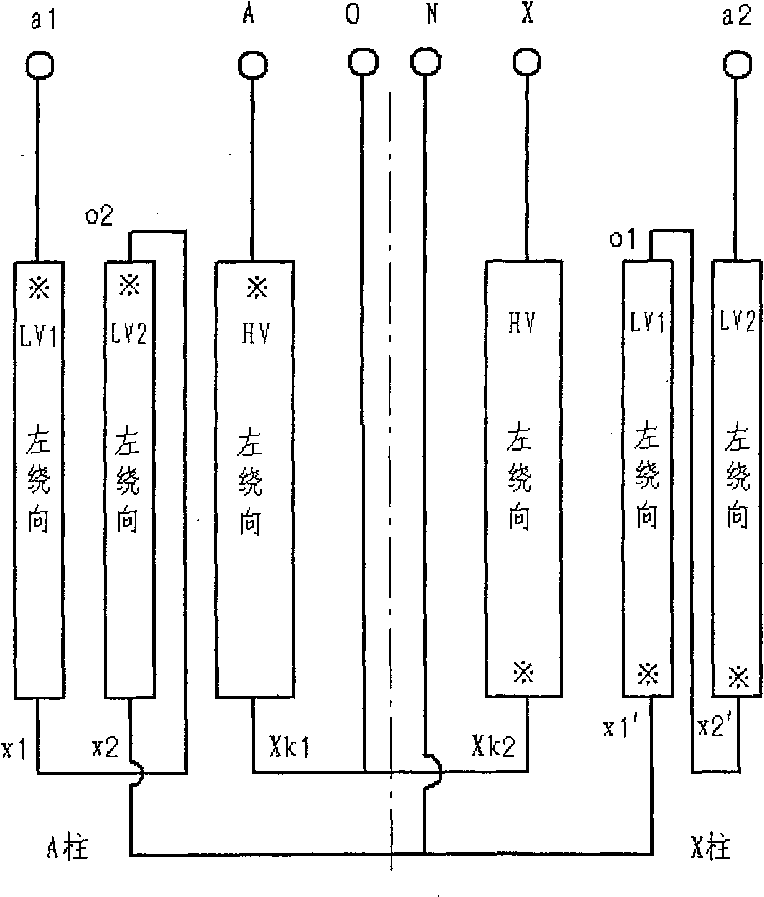
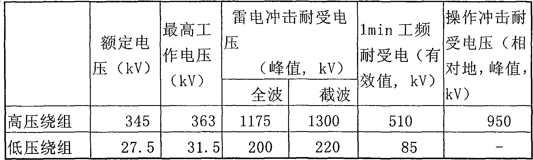
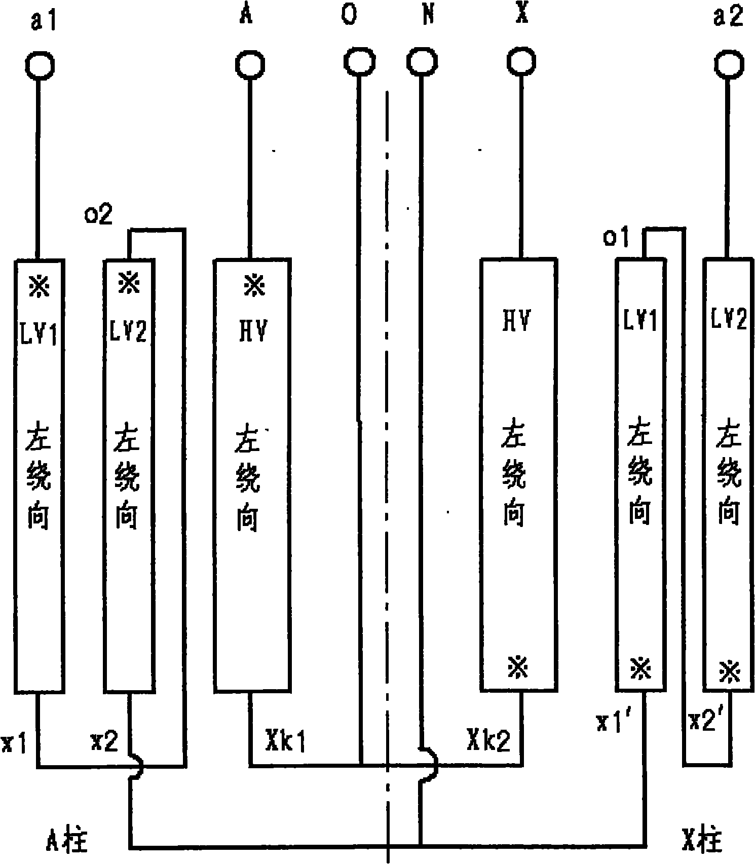
[0017] When a traditional transformer is subjected to a sudden short-circuit test, the rated voltage is usually applied to the primary side of the transformer winding, and the secondary side of the winding is short-circuited. At this time, the short-circuit current flowing through the primary side of the winding is measured as the short-circuit peak current. However, for ultra-high voltage transformers of 330kV and above, if the above traditional test method is used for the test, the test power transformer must be of a voltage level of 330kV and above, and the current test transformer is usually 220kV, which cannot meet the test requirements.

[0018] By adopting the test method of the present invention, the short-circuit peak current detection of the ultra-high voltage transformer of 330kV and above can be carried out by using the test transformer of low voltage level.

[0019] The present invention will be described in further detail below with reference to the embodiments an...


PUM


Abstract

The invention discloses a test method of a transformer, which comprises the following steps of: (1) leading out the head ends and the tail ends of two high-voltage windings which are connected in series and are respectively wound on the A pole and the X pole of a single-phase transformer respectively, then tapping at the middle parts of the high-voltage windings and leading out a joint O; (2) leading out the head ends and the tail ends of low-voltage windings which are connected in series and are respectively wound on the A pole and the X pole of the single-phase transformer as a1 and a2 respectively, then tapping at the middle parts of the low-voltage windings, leading out a joint N and grounding the joint N; (3) carrying out short-circuit test on coils on the A / X pole: adding test voltage between the A and the O of a primary side and short-circuiting the joints a1 and N; or, adding the test voltage between the X and the O of the primary side and short-circuiting the joints a2 and N; and (4) measuring the value of the current of the high-voltage windings, which flows through the A / X pole, wherein short-circuit current flowing through the coils of each pole is just an actual short-circuit current peak value. The method can finish the detection of the short-circuit peak current of an extra-high voltage transformer by a test transformer with low voltage class and achieves a test aim.

Description

technical field [0001] The invention belongs to the technical field of transformers, and relates to a test method of a transformer, in particular to a test method of a single-phase transformer. Background technique [0002] The traditional method for sudden short-circuit test of transformers is as follows. The rated voltage is applied to the primary side, and the secondary side is short-circuited. The short-circuit current flowing through the primary side is measured as the short-circuit peak current, so as to determine whether the short-circuit peak current is within Within the allowable range, the above test method has no problem for low-voltage transformers, but for ultra-high voltage transformers of 330kV and above, the main disadvantage of this test method is that the test power transformer must be 330kV voltage level, and its investment cost is large. At present, there is no special test transformer for short-circuit test of this voltage level in China (the current tes...

Claims


Application Information

Patent Timeline
IPC IPC(8): G01R19/04G01R31/06
Inventor 孟杰高德满蒋立金杨守辉孙建新徐寨新
Owner TEBIAN ELECTRIC APP CO LTD
Why Eureka
Try Eureka