Forced circulation continuous crystallization system with mechanical vapor recompression function
A forced circulation, mechanical steam technology, applied in the direction of solution crystallization, can solve the problems of wasting the latent heat of secondary steam, unenvironmental and economical, wasting energy, etc., and achieve the effect of eliminating condensation equipment, increasing corporate profits, and reducing costs.
- Summary
- Abstract
- Description
- Claims
- Application Information
AI Technical Summary
Problems solved by technology
Method used
Image

Examples
Embodiment Construction
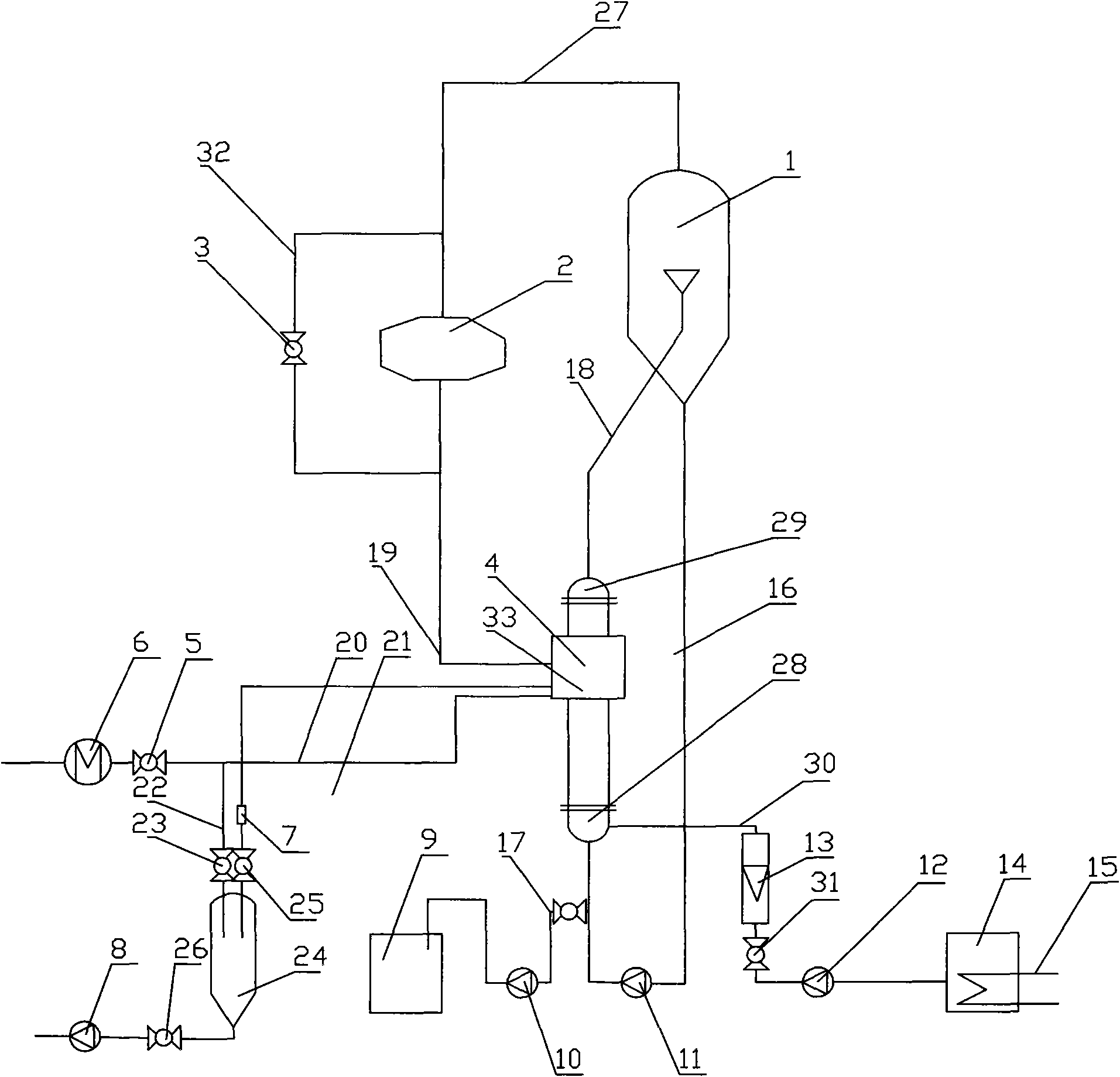
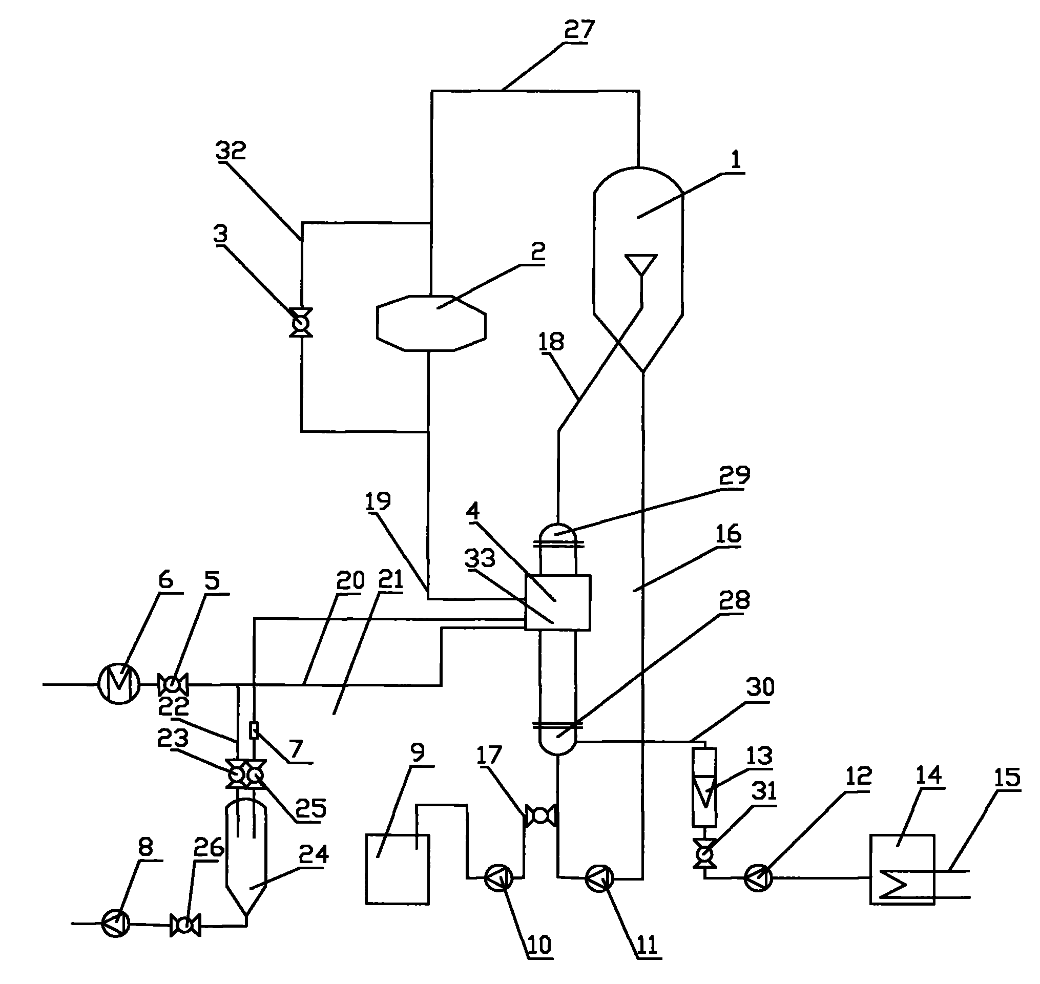
[0013] Such as figure 1 As shown, the forced circulation continuous crystallizer with mechanical vapor recompression includes a crystallizer 1, a compressor 2, a heater 4, a circulation pipe 16 is arranged at the bottom of the crystallizer 1, a circulation pump 11 is arranged on the circulation pipe 16, and after the circulation pump 11 A discharge pipe 17 is provided, a discharge pump 10 is provided behind the discharge pipe 17, a finished product tank 9 is provided at the end of the discharge pipe 17, the top of the crystallizer 1 is connected with the inlet of the compressor 2 through a pipeline 27, and the lower part of the heater 4 is provided with a The upper part of the head 28 is provided with an upper head 29, the bottom of the lower head 28 is connected with the circulation pipe 16, and the side of the lower head 28 has a feed pipe 30, and the feed pipe 30 is provided with a flow meter 13, a ball valve 31 and a feed pump 12. The end of the feed pipe 30 is connected t...
PUM
 Abstract
Description
Claims
Application Information
PatSnap Eureka turns technology decisions into work you can execute. Powered by our Innovation Knowledge Graph, it runs expert workflows across engineering, life sciences, materials and intellectual property. Get your review-ready output in minutes.


