Protector for preventing three-phase power circuit from generating high voltage
A technology of three-phase power supply and power circuit, applied in the direction of automatic disconnection emergency protection device, circuit device, emergency protection circuit device, etc., can solve the problems of no opening, rising, three-phase power supply lacking phase and zero, etc., to achieve The effect of simple structure and small volume
- Summary
- Abstract
- Description
- Claims
- Application Information
AI Technical Summary
Problems solved by technology
Method used
Image
Examples
Embodiment 1
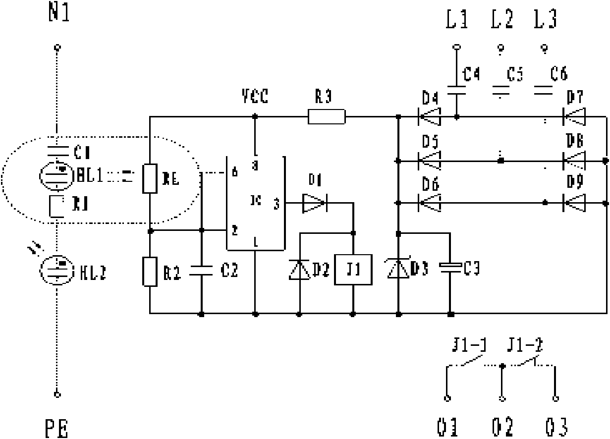
[0021] Embodiment 1: as figure 1 As shown, it is a schematic structural diagram of a protector circuit for preventing high voltage from being generated by a three-phase power supply circuit. It is composed of a power supply circuit, a zero-break detection circuit and a control output circuit. PE, where L1, L2, L3 are respectively connected to the output terminals L1, L2, L3 of the power switch K, N1, PE are respectively connected to the zero line N and the PE terminal of the protective grounding line, and the three output terminals 01, 02, 03, where terminals 01 and 02 are respectively connected to the control terminals 01 and 02 of the tripping coil L of the power switch K, and are connected to the input terminals A, B and C of the power switch K respectively to the A phase, B phase and C phase of the power supply connected.
[0022] After the three-phase power supply is input through terminals L1, L2, and L3, it is stepped down by capacitors C4--C6 respectively, and after t...
Embodiment 2
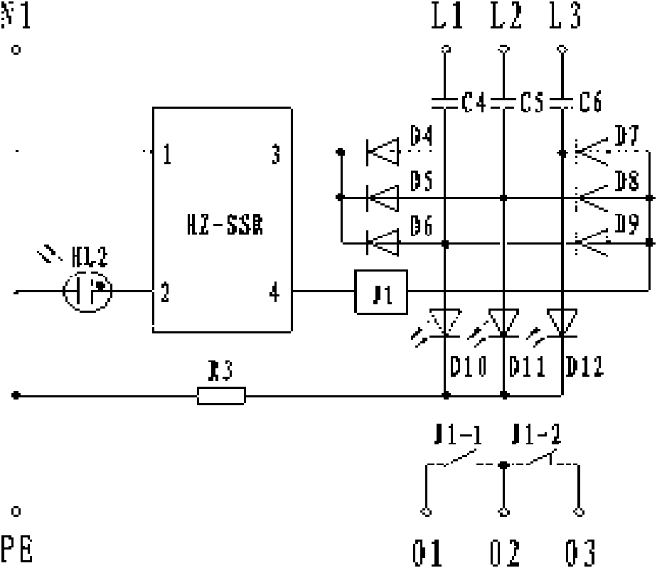
[0023] Embodiment 2: as figure 2 As shown, it is a schematic structural diagram of the second protector circuit for preventing high voltage from being generated by a three-phase power supply circuit of the present invention. It is composed of a power supply circuit and a high impedance solid state relay HZ-SSR circuit. The present invention has five input terminals L1 and L2 , L3, N1, PE are respectively connected to the output terminals L1, L2, L3 of the power switch K, N1, PE are respectively connected to the zero line N and the PE terminal of the protective grounding line, and the three output terminals 01, 02, 03 , where terminals 01 and 02 are respectively connected to terminals 01 and 02 of the tripping coil L of the power switch K, and are connected to the input terminals A, B and C of the power switch K respectively to phase A, phase B and phase C of the power supply .
[0024] After the three-phase power supply is input through terminals L1, L2, and L3, it is steppe...
Embodiment 3
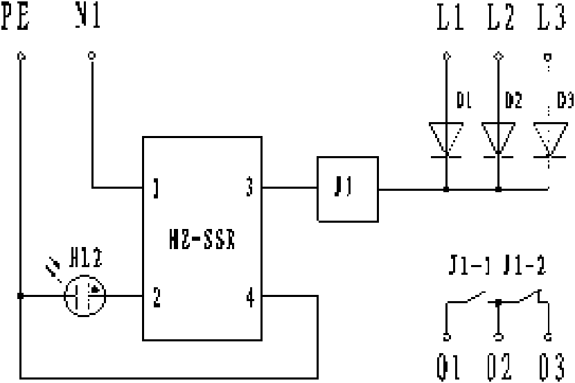
[0026] Embodiment 3: as image 3 , Figure 5 As shown, it is a schematic structural diagram of the third protector circuit for preventing high voltage from being generated by a three-phase power supply circuit of the present invention, which is composed of a power supply circuit and a high-impedance solid-state relay HZ-SSR circuit. . , where terminals 01 and 02 are respectively connected to the control terminals 01 and 02 of the tripping coil L of the power switch K, and are connected to the input terminals A, B and C of the power switch K respectively to the phase A, phase B and phase C of the power supply connect.
[0027]After the three-phase power supply is input through terminals L1, L2, and L3, after three-phase half-wave rectification by diode D1, the output pulsating DC voltage is connected in series with relay J1, and then connected to pin (3) of high-impedance solid-state relay HZ-SSR , the output terminal (4) of the high-impedance solid-state relay is connected ...
PUM
 Abstract
Description
Claims
Application Information
 - R&D
- Intellectual Property
- Life Sciences
- Materials
- Tech Scout
- Unparalleled Data Quality
- Higher Quality Content
- 60% Fewer Hallucinations
Browse by: Latest US Patents, China's latest patents, Technical Efficacy Thesaurus, Application Domain, Technology Topic, Popular Technical Reports.
© 2025 PatSnap. All rights reserved.Legal|Privacy policy|Modern Slavery Act Transparency Statement|Sitemap|About US| Contact US: help@patsnap.com


