
Methods and apparatus for a permanent magnet machine with a direct liquid cooled stator

A permanent magnet motor and stator technology, which can be used in cooling/ventilation devices, synchronous machines, electromechanical devices, etc., and can solve problems such as inefficiency and large housing.

Active Publication Date: 2010-11-03
GM GLOBAL TECH OPERATIONS LLC
View PDF3 Cites 11 Cited by
  • Summary
  • Abstract
  • Description
  • Claims
  • Application Information

AI Technical Summary

Problems solved by technology

Currently used fluid cooling methods involve flowing some form of cooling fluid (such as water glycol, WEG) within the cooling assembly and housing, however the housing is large, inefficient, and requires complex fixturing to Works in conjunction with the stator itself

Method used


Image

  • Methods and apparatus for a permanent magnet machine with a direct liquid cooled stator
  • Methods and apparatus for a permanent magnet machine with a direct liquid cooled stator
  • Methods and apparatus for a permanent magnet machine with a direct liquid cooled stator

Examples


Embodiment Construction

[0041] The following detailed description is merely exemplary in nature and is not intended to limit the invention or its application and uses. Furthermore, there is no intention to be bound by any expressed or implied theory presented in the preceding technical field, background, brief summary or the following detailed description. The invention may be described herein in terms of functional and / or logical block components and various processing steps. It should be appreciated that such block components may be realized by any number of hardware, software, and / or firmware components configured to perform the specified functions. For the sake of brevity, conventional techniques and systems involving electric motors, magnetics, etc. are not described herein.

[0042] In general, the various embodiments are directed to permanent magnet motors ("PM motors") having a stator assembly that incorporates cooling passages or fins within the stator body, and is configured to add heat to...


PUM


Abstract

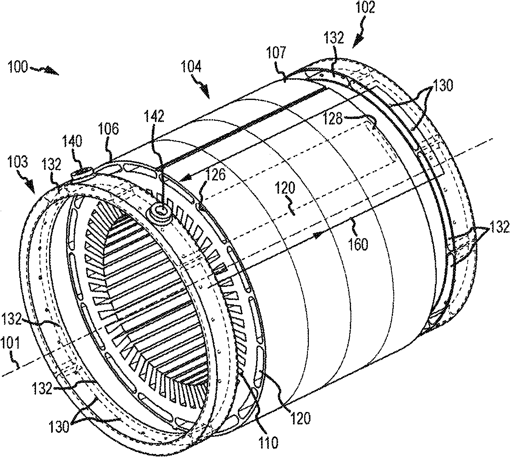
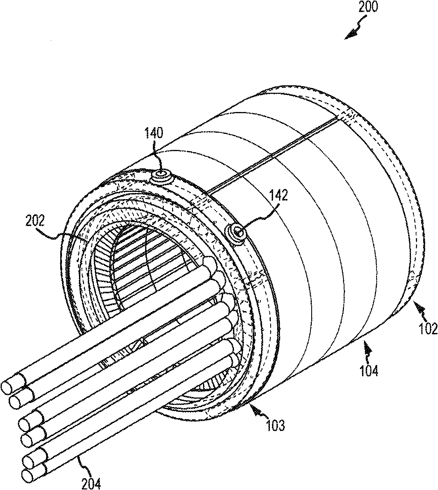
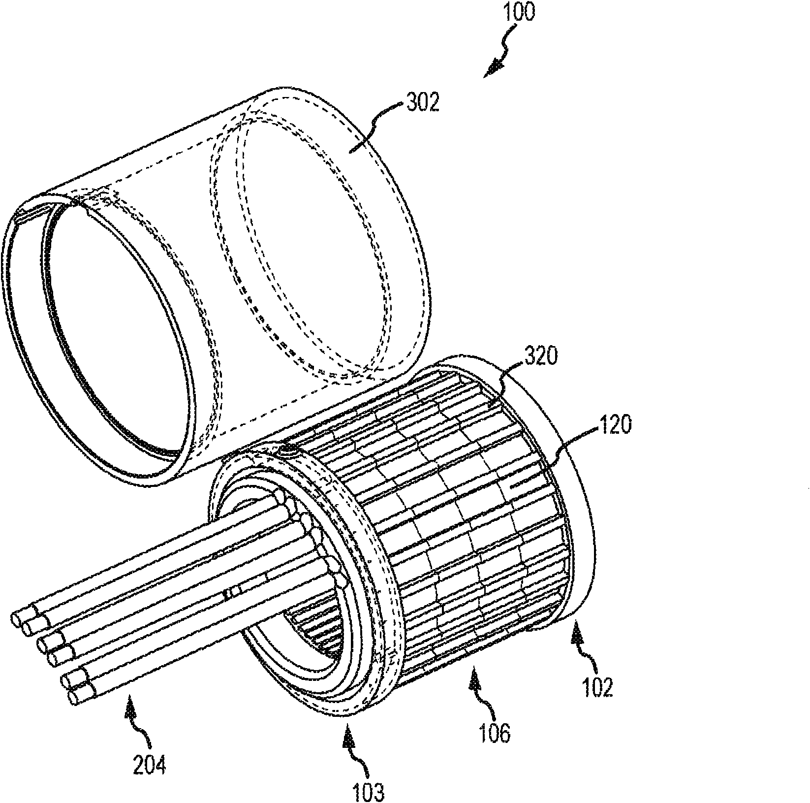
The invention relates to methods and apparatus for a permanent magnet machine with a direct liquid cooled stator. The permanent magnetic machine includes a stator body having a first end, a second end, and a plurality of generally radial slots formed therein for accepting a set of windings having a first set of end-turns at the first end and a second set of end-turns at the second end. The statorbody has a plurality of channels adjacent to the slots and extending from the first end of the stator body to the second end of the stator body, wherein the channels are configured to allow the flow of a cooling fluid therethrough. A plurality of nozzles in fluid communication with the plurality of channels are configured to spray the cooling fluid onto the first and second set of end turns.

Description

technical field [0001] The present invention relates generally to magnetic devices such as electric motors, and more particularly to cooling methods for interior permanent magnet electric machines. Background technique [0002] Permanent magnet (PM) motors are suitable for operation of fuel cell and hybrid electric vehicles due to their desirable properties (ie, good torque density, good overall efficiency, good constant power range, etc.). Unlike other motors, such as induction, commutation or synchronous reluctance motors where the rotor field is generated by the stator current supplied by the source, the rotor field in a permanent magnet motor is due to its structure. Therefore, permanent magnet motors have higher efficiency than these other motors. [0003] However, cooling of such PM motors is a tricky problem, especially with respect to the cooling of the heat generated at the end turns of the windings (at the opposite end of the stator stack) and within the stator bo...

Claims


Application Information

Patent Timeline
IPC IPC(8): H02K1/20H02K21/00
CPCH02K1/20H02K9/19
Inventor D·D·党E·哈奇R·布利森巴赫K·乐J·伯德
Owner GM GLOBAL TECH OPERATIONS LLC
Learn More