Dipping type film-separating apparatus, and film cartridge

A separation device and submerged membrane technology, which is applied in the direction of semi-permeable membrane separation, membrane, membrane technology, etc., can solve problems such as the inability of suction pressure to improve safety, reduce labor, and reduce the danger of heights The effect of homework

Active Publication Date: 2014-11-12
KUBOTA CORP
View PDF6 Cites 4 Cited by
  • Summary
  • Abstract
  • Description
  • Claims
  • Application Information

AI Technical Summary

Problems solved by technology

Even in this case, since only the water intake nozzle on the upper end of the bellows is used in the filtration operation, as above, sufficient suction pressure cannot be applied to the lower part of the bellows, and the shape of the bellows is different. However, it is difficult to effectively use the whole filter membrane and obtain the filtrate

Method used


Image

  • Dipping type film-separating apparatus, and film cartridge
  • Dipping type film-separating apparatus, and film cartridge
  • Dipping type film-separating apparatus, and film cartridge

Examples


Embodiment Construction

[0096] Next, a first embodiment of the present invention will be described with reference to the drawings.

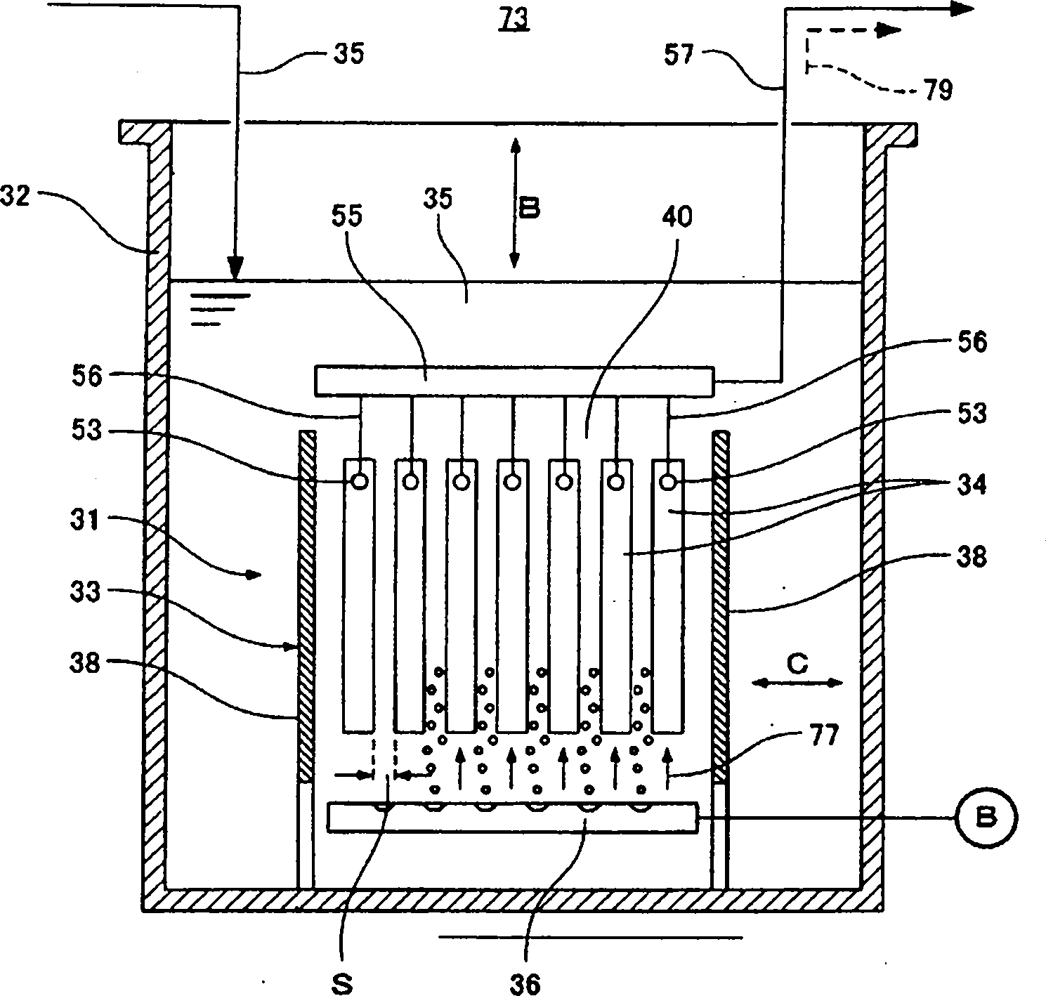
[0097] Such as figure 1 As shown, 31 is a submerged membrane separation device. This submerged membrane separation device 31 is immersed in a treatment tank 32 and is used to separate activated sludge and treated water. The submerged membrane separation device 31 has a box-shaped membrane casing 33 with upper and lower openings, a plurality of flat-plate-shaped membrane boxes 34 arranged in parallel to each other inside the casing 33, and arranged below these membrane boxes 34. The air diffuser 36.

[0098] In addition, the air diffusion device 36 is an example of a liquid flow generating device that generates a rise along the membrane surface of the diaphragm case 34 by ejecting air from a plurality of ejection holes formed in the air diffusion pipe. Flow 77 (an example of liquid flow in one direction).

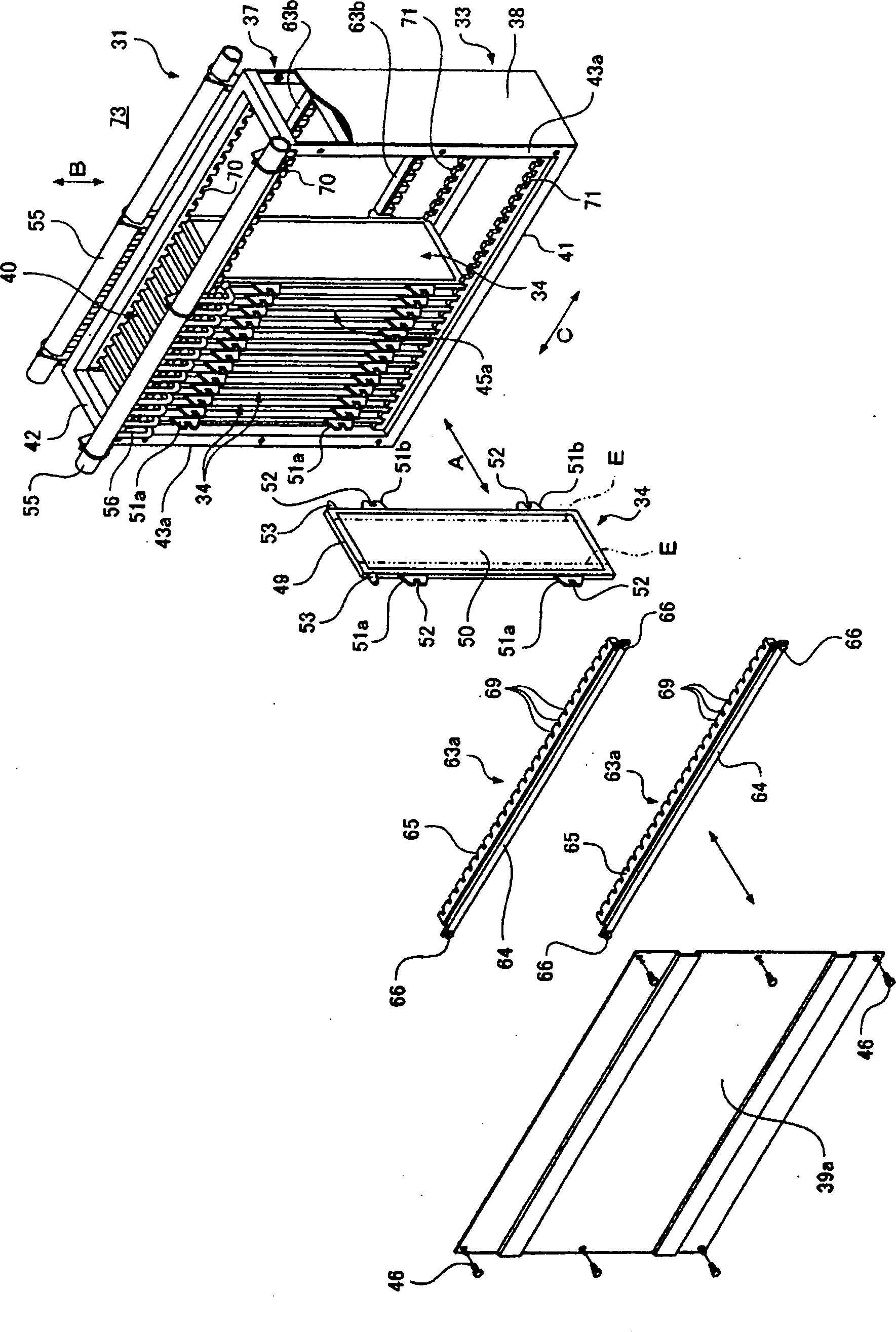
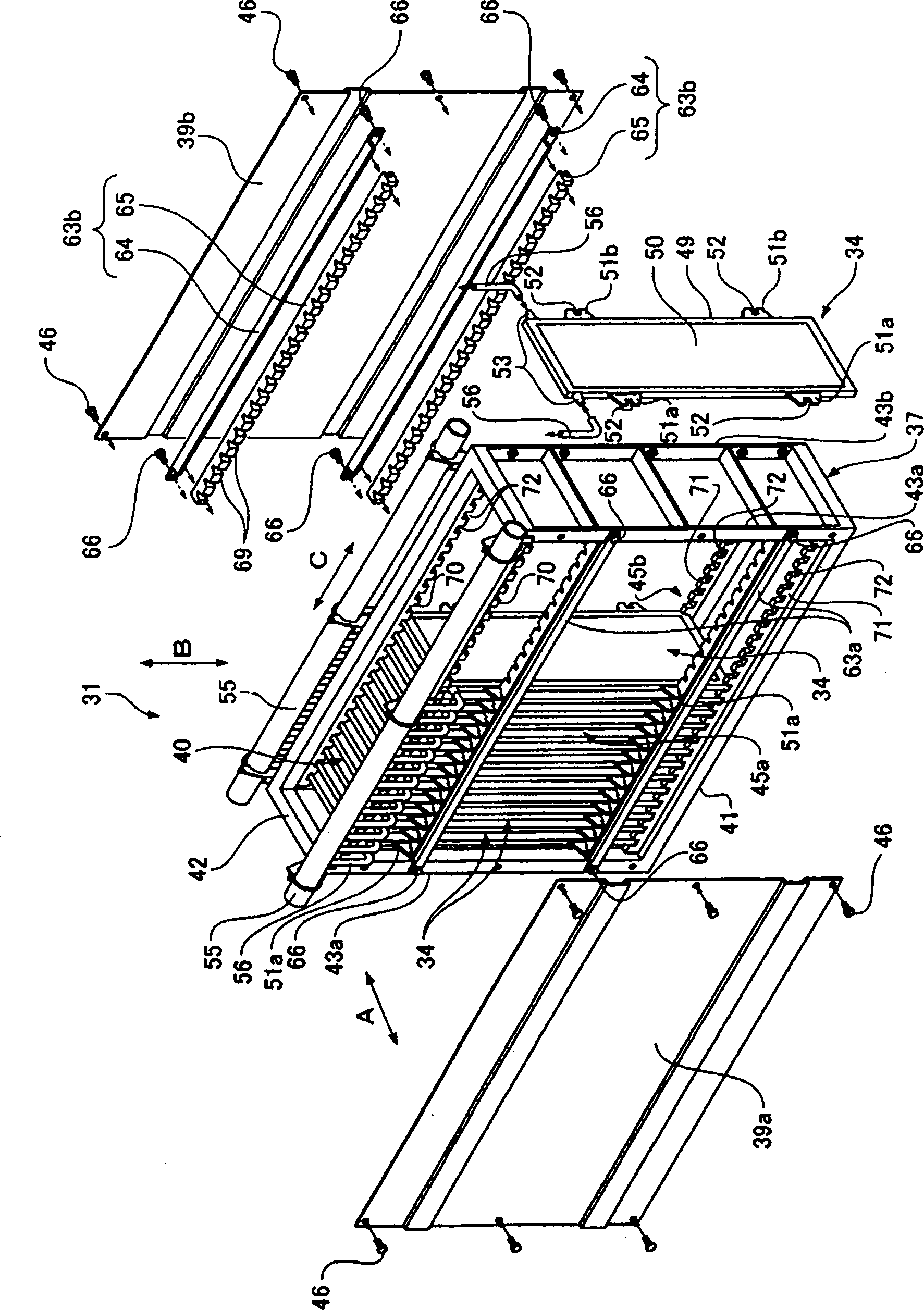
[0099] Such as figure 2 , image 3 As shown, in the inst...


PUM


Abstract

A submerged membrane separator includes: a plurality of membrane cartridges arranged at predetermined spaces; a flow generating device for generating flows in one direction along the membrane surfaces of the membrane cartridges; and wall members on both sides of a channel of the flow in the one direction formed between the membrane cartridges adjacent to each other. The membrane cartridges can be attached and detached from another direction substantially orthogonal to the flows in the one direction and substantially orthogonal to the arrangement direction of the membrane cartridges.

Description

technical field [0001] The present invention relates to a submerged membrane separation device immersed in, for example, a liquid to be treated disposed in a treatment tank, and a membrane cassette installed in the submerged membrane separation device as described above. Background technique [0002] In the past, as this submerged membrane separation device, such as Figure 28 ~ Figure 3 As shown in 0, there is a device that is immersed in a treatment tank to separate activated sludge and treated water. The submerged membrane separation device 1 has a box-shaped housing 2 with upper and lower openings, a plurality of elongated membrane cassettes 3 arranged in parallel to each other in the housing 2 , and an air diffuser 4 disposed below the membrane cassettes 3 . [0003] A water intake nozzle 6 is provided on the upper end of the membrane box 3, and the water intake nozzle 6 is used to suck the treated water 5 obtained through membrane filtration. A plurality of vertically...

Claims


Application Information

Patent Timeline
Patent Type & Authority Patents(China)
IPC IPC(8): B01D63/08
CPCB01D65/025B01D2315/06B01D61/18B01D63/082B01D2321/02B01D2313/56B01D2313/02B01D2313/06B01D63/0821B01D63/0822
Inventor 松崎好男石川公博上岛达也佐佐木智彦
Owner KUBOTA CORP
Why Eureka
Try Eureka