
Two-speed wind distributing method for blast furnace blower

A blower and blast furnace technology, which is applied to blast furnaces, blast furnace details, blast furnace parts, etc., can solve problems such as blast furnace blower load not keeping up, performance loss of blower blast furnace, blast furnace blower equipment damage, etc., to eliminate faulty blast furnace slag filling accidents, ensure non-slag filling operation, and reduce the effect of accident economic losses

Inactive Publication Date: 2010-11-10
ANGANG STEEL CO LTD
View PDF0 Cites 4 Cited by
  • Summary
  • Abstract
  • Description
  • Claims
  • Application Information

AI Technical Summary

Problems solved by technology

At present, the opening time of the fast valve installed in the system is 5-8 seconds. Although it meets the needs of the faulty blast furnace, the rapid blowing has caused the performance loss of the blown blast furnace, because the wind pressure drops rapidly, causing the blown blast furnace The condition is instantly destroyed, and at the same time, the blast furnace online blower must meet the 1500Nm within 5-8 seconds 3 / min load increase is unrealistic
Moreover, the instantaneous excessive adjustment often causes damage to blast furnace blower equipment, thereby expanding the scope of the accident
As a result, the load of the blast furnace blower running during the blowing process cannot keep up, and the unfavorable consequences of the unstable condition of the blast furnace being blown

Method used


Image

  • Two-speed wind distributing method for blast furnace blower
  • Two-speed wind distributing method for blast furnace blower
  • Two-speed wind distributing method for blast furnace blower

Examples


Embodiment Construction

[0013] Specific embodiments of the present invention will be described in detail below in conjunction with the accompanying drawings.

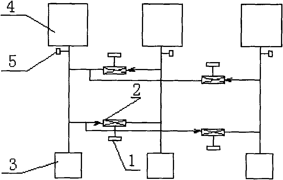
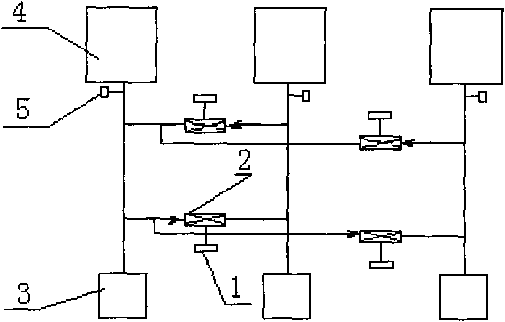
[0014] Such as figure 1 As shown, DCS and PLC control system 5 are installed on multiple air blowers 5 of each blast furnace 4 of the present invention (generally, a blast furnace is equipped with 4 to 6 air blowers) to realize constant monitoring and interlock control, and two-speed air blowers are configured between each other. The blower device 1 adopts multi-machine interconnection, automatic judgment after failure, and automatic blower, and uses a double-speed blower to perform double-speed blower blower to ensure the safe and normal operation of the blast furnace and blast furnace blower.

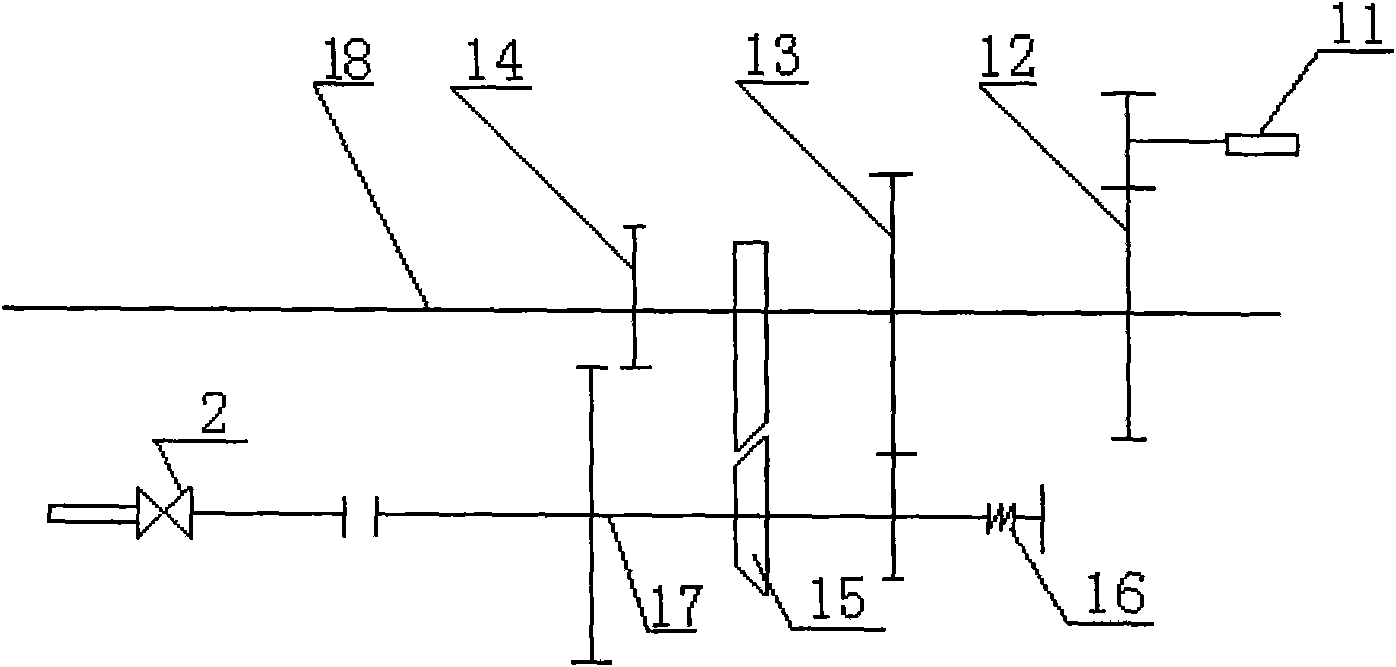
[0015] According to the present invention, the double-speed fan adopts a double-speed motor or a mechanical double-speed control device to control the opening of the angle of the valve 2 in sections. 30%-40% of the flow rate of the valve, the air vol...


PUM


Abstract

The invention discloses a two-speed wind distributing method for a blast furnace blower. The method adopts a running way combining a DCS (Distributed Control System) with a PLC (Programmable Logic Controller) system, and is characterized by adopting multi-machine interconnection, automatic judgment after failure, and automatic wind distributing and carrying out two-speed wind distributing on the blower. In the double-speed wind distributing method, the angle of a wind distributing valve is opened by sections, and in the opening method, the opening time is 3-5 seconds in first 20 degrees to ensure that the flow quantity reaches 30%-40% of the total flow quantity of the valve; and the opening time is 30-40 seconds in last 70 degrees so as to ensure that the throttling valve reaches maximum flow quantity in the time period. By adopting the measure of carrying out two-speed controlled wind distributing on the failed blast furnace blower, the invention stably increases the loads on the blast furnace blower subjected to wind distributing, ensures the pressure of the blast furnace to slowly and stably fluctuate, reduces the economic loss of accidents, effectively ensures the failed blast furnace not to run with slag pouring, and eliminates the slag pouring accident of the failed blast furnace, caused by delayed artificial operation.

Description

technical field [0001] The invention belongs to a control system of a blast furnace blower, in particular to a two-speed blowing method for a blast furnace blower. Background technique [0002] At present, the blast furnace blower online operation system is connected to the air supply system by the system connection pipeline, which serves the purpose of having a backup fan in the daily production of the blast furnace. However, the defect of this system is that if the blast furnace blower fails due to its own equipment or external factors, the standby blast furnace blower will restart to supply air for it. It takes about 10 minutes for the electric blower and 1 hour and 30 minutes for the steam blower. . In this case, the accident avoidance time of the blast furnace is at most within 3-5 minutes. Otherwise, it will cause blast furnace slag filling accident. It is obvious that our current system cannot satisfy the safe operation of the blast furnace. [0003] In order to a...

Claims


Application Information

Patent Timeline
IPC IPC(8): C21B9/10
Inventor 刘加纯
Owner ANGANG STEEL CO LTD
Learn More