Cross-flow type air handling device

A cross-flow air and treatment device technology, applied in heating mode, air conditioning system, space heating and ventilation, etc., can solve the problem of low heat and mass transfer efficiency, complex structure of multi-stage dehumidification and regeneration device, and large solution temperature slip and other problems to achieve the effect of avoiding the decline of heat and mass transfer capacity, avoiding the entrainment of solution droplets, and being easy to obtain.

Inactive Publication Date: 2010-11-10
UNIV OF SHANGHAI FOR SCI & TECH
View PDF3 Cites 7 Cited by
  • Summary
  • Abstract
  • Description
  • Claims
  • Application Information

AI Technical Summary

Problems solved by technology

[0004] The invention discloses a cross-flow air treatment device, aiming at overcoming the large solution temperature slip and low heat and mass transfer efficiency existing in the existing air deh

Method used


Image

  • Cross-flow type air handling device
  • Cross-flow type air handling device

Examples


Embodiment Construction

[0013] The present invention will be described in further detail below in conjunction with accompanying drawing and embodiment, but present embodiment is not intended to limit the present invention, and every adopt similar structure of the present invention and similar change thereof, all should be included in the protection scope of the present invention.

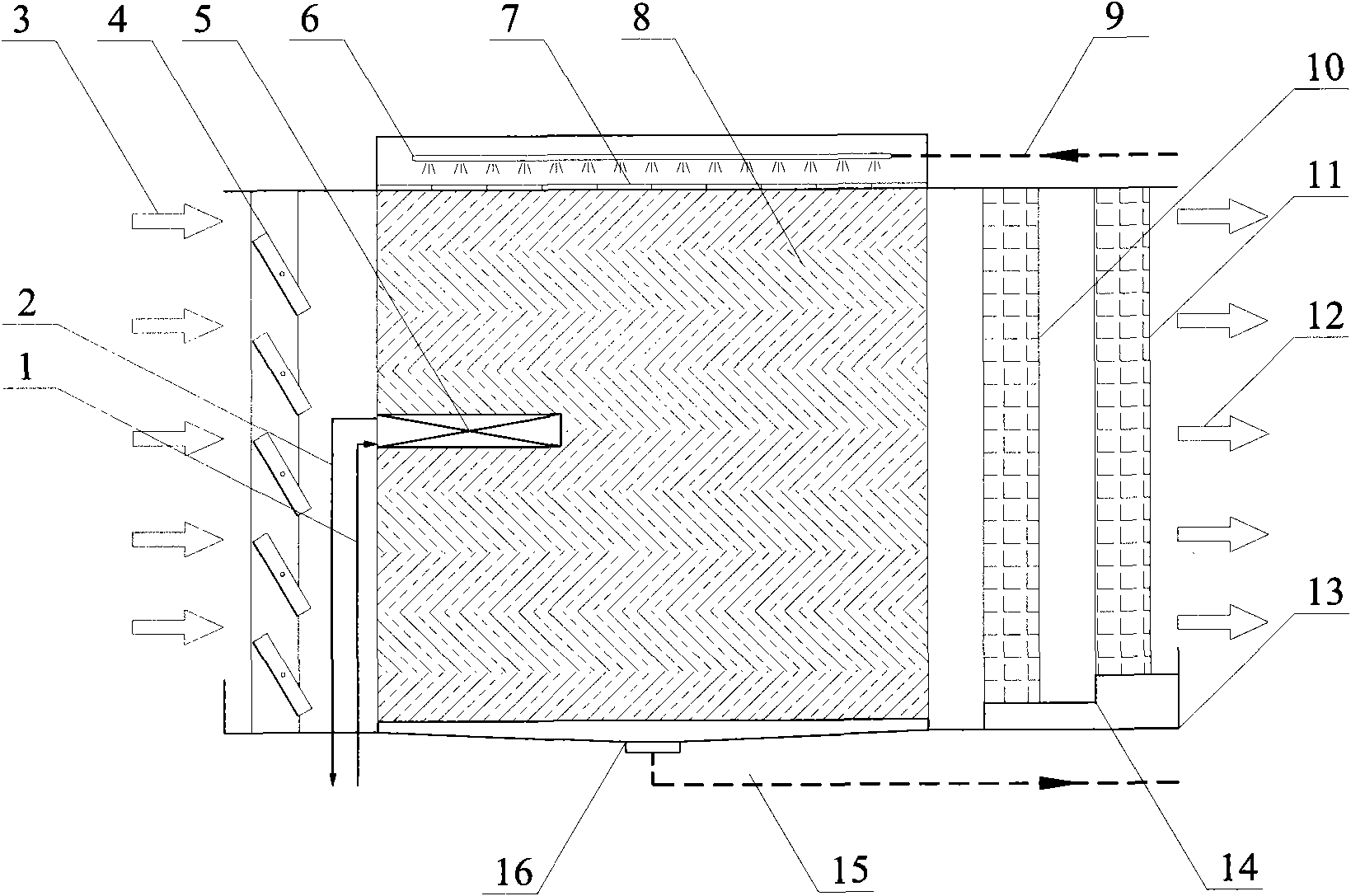
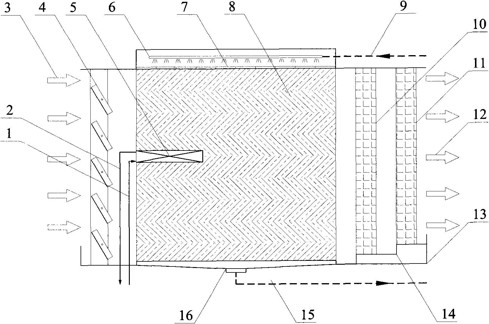
[0014] A cross-flow air treatment device, comprising: stagnant liquid louvers 4, packing layer 8, liquid distributor, defoaming layer and liquid collection tray 13, characterized in that: the air inlet 3 in front of the packing layer 8 is provided with blades for rotation Adjustable stagnant louvers 4, the primary effect defoaming layer 10 and the final effect defoaming layer 11 are arranged in sequence at the air outlet 12 behind the packing layer 8, and the primary liquid distributor 6 is arranged above the packing layer; the primary liquid distributor 6 It is connected with the solution inlet pipe 9, the final liquid dis...


PUM


Abstract

The invention relates to a cross-flow type air handling device, comprising a viscous-liquid shutter, a packing layer, liquid distributors, defoaming layers and a liquid collecting disc, wherein the front of the packing layer is provided with the viscous-liquid shutter; the rear of the packing layer is provided with a primary-effect defoaming layer and a final-effect defoaming layer; a primary liquid distributor is arranged above the packing layer and is connected with a solution inlet pipe; a final liquid distributor is arranged below the primary liquid distributor; the middle part of the packing layer is provided with a cooling/heating coil; a water inlet and a water inlet pipe of the cooling/heating coil are connected, and a water outlet and a water outlet pipe thereof are connected; the bottom parts of the packing layer, the primary-effect defoaming layer and the final-effect defoaming layer are arranged on the liquid collecting disc; and the bottom part of the liquid collecting disc is provided with a solution backflow port which is connected with a solution distributing pipe. The cross-flow type air handling device utilizes a form of local inner cooling, two-stage solution distribution and two-stage defoaming to effectively improve heat and mass transferring efficiency of a cross-flow dehumidifying and regenerating device, not only has simple structure and convenient manufacture, but also effectively avoids the problems of air with liquid, solution splashing and the like.

Description

technical field [0001] The invention relates to a device for dehumidifying air with a solution and regenerating a solution with air, in particular to a cross-flow air treatment device, which belongs to the technical field of refrigeration and air conditioning. Background technique [0002] In recent years, under the dual pressure of energy and environment, liquid dehumidification air-conditioning system has gradually attracted the attention of professional technicians due to its advantages of using low-grade heat sources such as solar energy, industrial waste heat, waste heat, etc. to drive, save electricity, and protect the environment. Liquid dehumidification air conditioner is a new type of air conditioning refrigeration method that uses hygroscopic salt solution to dehumidify the air, and then uses evaporative cooling technology or other refrigeration technology to cool the air to achieve the air supply state of the air conditioner. At the same time, the salt solution abs...

Claims


Application Information

Patent Timeline
IPC IPC(8): F24F3/14F24F13/30
Inventor 王瑾柳建华张海江张良孔丁峰方志云葛其林王素英辛晶晶
Owner UNIV OF SHANGHAI FOR SCI & TECH
Why Eureka
Try Eureka