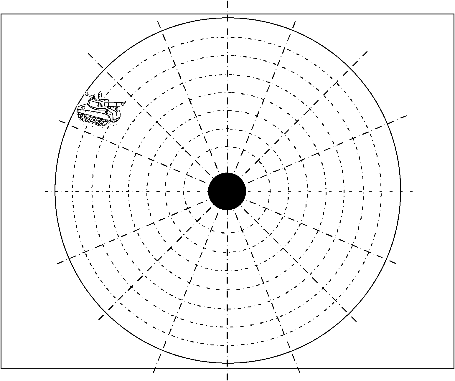
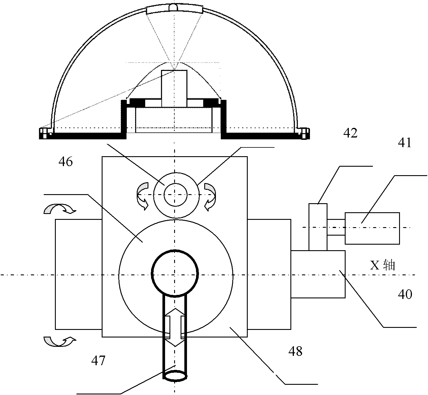
[0032] The present invention will be further described below in conjunction with the drawings.
[0033] Reference Figure 1~Figure 11 , A rapid automatic aiming device for artillery, including an omnidirectional vision sensor, an embedded system, a touch screen, a periscope aiming drive unit, and a periscope aiming mechanism; the omnidirectional vision sensor is used to obtain the surrounding area of the tank Panoramic video image, fixed on the top of the outer artillery turret of the tank, such as Image 6 As shown; the embedded system is used to read the panoramic video image obtained from the omnidirectional vision sensor and the partial video image of the attacking target obtained from the periscope sighting mechanism, and is used to obtain The control signal of the touch display screen is used to control the periscope aiming drive unit, and the embedded system is arranged inside the tank and near the periscope aiming drive unit; The touch screen is used to display the panoramic video images around the tank and the partial video images of the attacking target, for providing the gunner with the suspicious attacking target and confirming the attacking target, and for providing the gunner with control of the periscope The aiming mechanism is used to aim at the target; the periscope aiming drive unit is used to receive the serial control signal from the embedded system, and is used to drive the periscope aiming mechanism so that the periscope can be obtained clearly The target image of the attacker;
[0034] The omnidirectional vision sensor includes a camera unit 3, a primary catadioptric mirror 4, a secondary catadioptric mirror 5, a wide-angle lens 6 and an outer cover 2. The incident light V1 of a light source point P in space is on the primary catadioptric mirror 4 (t1 , F 1 ) Point, and the reflected light V2 is reflected to the double refractive mirror surface 5 (t2, F 2 ) Is reflected again at the point, and the reflected light V3 enters the lens of the camera device at an angle θ1, and forms an image on the camera unit 3 (CCD or CMOS);
[0035] According to the principle of omni-directional imaging, the angle between the primary incident light V1 and the principal axis Z is Ф, and the angle between the primary reflected light V2 and the principal axis Z is θ 2 , Over P 1 Point (t 1 , F 1 The angle between the tangent of) and the t axis is σ, and the angle between the normal and the Z axis is ε; the angle between the secondary reflected light V3 and the principal axis Z of the refraction is θ 1 , Over P 2 Point (t 2 , F 2 The angle between the tangent of) and the t axis is σ, and the angle between the normal and the Z axis is ε 1 , Based on the above relationship, formula (1) can be obtained:
[0036]
[0037] among them tan φ = t 1 F 1 ( t 1 - s ) , tan θ 2 = t 1 - t 2 F 2 - F 1 , tan θ 1 = t 2 F 2
[0038] In the formula, F 1 Is a catadioptric mirror curve, F 2 It is a double refractive mirror curve;
[0039] Using the triangle relationship and simplifying and sorting, the formulas (2) and (3) are obtained:
[0040] F 1 ′ 2 - 2 α F 1 ′ - 1 = 0 - - - ( 2 )
[0041] F 2 ′ 2 - 2 β F 2 ′ - 1 = 0 - - - ( 3 )
[0042] In the above formula,
[0043] σ = ( F 1 - s ) ( F 2 - F 1 ) - t 1 ( t 1 - t 2 ) t 1 ( F 2 - F 1 ) - ( t 1 - t 2 ) ( F 1 - s )
[0044] β = t 2 ( t 1 - t 2 ) + F 2 ( F 2 - F 1 ) t 2 ( F 2 - F 1 ) - F 2 ( t 1 - t 2 )
[0045] Solving formulas (2) and (3) can get formulas (4) and (5);
[0046] F 1 ′ = α ± α 2 + 1 - - - ( 4 )
[0047] F 2 ′ = β ± β 2 + 1 - - - ( 5 )
[0048] Where: F′ 1 For F 1 Differential of the curve, F′ 2 For F 2 Differential of the curve;
[0049] The relationship between the points on the imaging plane and the points on the horizontal plane has a certain linear relationship. Any point P on the horizontal plane L whose distance from the viewpoint S is C and perpendicular to the Z axis is in the imaging plane There is a corresponding pixel p on the above, as attached Picture 10 As shown, the coordinates on the horizontal plane are expressed in polar coordinates. At this time, any point P(r, z) on the horizontal plane L can be expressed by the following formula:
[0050] r=C*tanφ, z=s+C (6)
[0051] In order to design an omni-directional vision sensor with an average resolution on the horizontal plane, that is, an omni-directional vision sensor that does not deform in the horizontal direction, the coordinate r of any point P on the horizontal plane L perpendicular to the Z axis and the distance between the pixel point p and the Z axis t 2 /F 2 (t 2 ) Must have a linear relationship. So that the following formula can be established,
[0052] r=a*f*t 2 /F 2 (t 2 )+b (7)
[0053] According to the imaging principle, the following relationship holds. The incident angle is expressed by formula (8),
[0054] tan φ = t 1 F 1 - s - - - ( 8 )
[0055] Substituting formulas (6) and (8) into formula (7) and sorting them out, the condition of no deformation in the horizontal direction is obtained, which is expressed by formula (9),
[0056] t 2 = F 2 ( t 2 ) a * f ( t 1 F 1 ( t 1 ) - s - b ) - - - ( 9 )
[0057] The mirror curve design that meets the formula (9) meets the requirements of the average horizontal resolution;
[0058] Furthermore, by using the fourth-order Runge-Kutta algorithm for formulas (2), (3), (9) to find F 1 And F 2 The digital solution of, so that the calculated primary and secondary refractive mirror curves can achieve the average resolution in the horizontal direction; Picture 9 Is to use the fourth-order Runge-Kutta algorithm to find F 1 And F 2 Reflective mirror curve diagram of the digital solution;
[0059] The transparent outer cover 2 is designed so that the transparent outer cover 2 will not produce interference light reflected by the inner wall, such as Figure 7 Shown. The specific method is to design the transparent cover into a bowl shape, that is, a semi-circular ball, which can avoid the reflection and interference light in the transparent cover 2. The structure of the omnidirectional vision sensor is as Figure 7 Shown
[0060] Figure 8 It is a diagram of the positional relationship between the camera unit lens and the wide-angle lens. Figure 8 The wide-angle lens is arranged in front of the primary catadioptric mirror and on the secondary catadioptric mirror, and the central axes of the camera unit lens, wide-angle lens, primary catadioptric mirror and secondary catadioptric mirror are arranged on the same axis; the lens of the camera unit It is placed at the viewpoint position at the rear of the first catadioptric mirror, and the image is formed between the wide-angle lens and the camera unit lens through the circular hole on the primary catadioptric mirror, which is called the first imaging point, which is at the viewpoint through the camera unit lens Imaging. Here the focal distance of the camera unit lens is taken as f1, the focal distance of the wide-angle lens is taken as f2, the distance between the camera unit lens and the focal point of the camera unit lens is taken as S1, the focal distance from the camera unit lens to the first imaging point is taken as S2, from the wide-angle lens to The distance of the first imaging point is taken as S3, and the distance from the wide-angle lens to the object point is taken as S4. According to the imaging formula of the lens, the following relationship can be obtained:
[0061] 1 f 1 = 1 S 1 + 1 S 2 - - - ( 10 )
[0062] 1 f 2 = 1 S 3 + 1 S 4 - - - ( 11 )
[0063] d=S2+S3 (12)
[0064] If formula (12) is to be established, it means that image 3 If you configure a wide-angle lens at a distance d from the camera unit lens behind the first catadioptric mirror, you can get figure 2 The wide-angle imaging image displayed in the middle of the image; but in the present invention, the wide-angle lens is arranged on the second catadioptric mirror surface, so the distance d between the camera unit lens and the wide-angle lens is taken as a constraint, only by designing the focal point of the wide-angle lens The distance f2 meets the requirements of formula (12);
[0065] for Figure 8 If the camera unit lens and the wide-angle lens are considered as a combined lens, the focal length f can be expressed by the following formula:
[0066] 1 f = ( f 1 + f 2 - d ) f 1 * f 2 - - - ( 13 )
[0067] In addition, taking the diameter of the synthetic lens as D, its magnification can be expressed by the following formula:
[0068] n = D f - - - ( 14 )
[0069] In order to match the field of view of the synthetic lens with the blind part of the omnidirectional vision sensor, the following formula needs to be satisfied when designing the synthetic lens:
[0070] n = D f = 2 θ 1 max - - - ( 15 )
[0071] Where θ 1max It is the maximum angle between the secondary reflected light V3 and the main axis Z of the catadioptric reflection; the image effect picture taken by the omni-directional vision sensor designed above is as follows Figure 5 As shown, it can effectively cover the blind part of the original omnidirectional vision sensor, that is, the gunner can observe the image above the tank on the screen;
[0072] The camera unit of the omnidirectional vision sensor is connected to the embedded system through a USB interface, and the camera unit of the periscope sighting mechanism is connected to the embedded system through a USB interface. The periscope sight drive unit is connected to the embedded system through an RS232/RS485 converter, and the periscope sight drive unit directly drives the periscope sight mechanism;
[0073] The periscope sight drive unit is equipped with a built-in decoder, and the embedded system sends a serial port command to the COM port through the serial port. After the periscope sight drive unit receives the serial port command, the control command Analyze and convert the parsed command into a corresponding control voltage capable of driving the rotation of the periscope targeting mechanism, and finally transfer the control voltage to the periscope targeting mechanism to control the periscope Operation of the horizontal rotation motor, the vertical rotation motor, the focusing and stopping of the periscope lens in the automatic sighting mechanism;
[0074] For the built-in decoder, its decoder control protocol controls the periscope sighting mechanism, and specifically adopts the PELCO-D control protocol as the control protocol for the periscope sighting mechanism;
[0075] The periscope sighting mechanism includes a rotating shaft 40, a first motor 41, a first gear 42, a second motor 44, a second gear 45, a third gear 46, a periscope 47 and a fixed frame 48, which are used as the first vertical rotation. A motor 41 drives the first gear 42 to rotate. The first gear 42 meshes with the external gear on the rotating shaft 40, so that the rotating shaft 40 is driven by the first motor 41 to rotate in a vertical plane. The vertical rotation control parameter is determined by the incident angle Ф. The mechanical device for horizontal rotation is installed on the fixed frame 48, and the fixed frame 48 is fixedly connected with the outer wall of the rotating shaft 40. Therefore, the driving of the first motor 41 can also drive the fixed frame 48 to rotate in the vertical plane; the fixed frame 48 The second motor 44, the second gear 45, the third gear 46 and the periscope 47 are fixed on the upper part. The second motor 44 drives the second gear 45 to rotate in the plane of the fixed frame 48. The second gear 45 and the third gear 46 Engaged, the upper part of the third gear 46 fixes the periscope 47, so the second motor 44 can also drive the periscope 47 to rotate in the plane of the fixed frame 48. The horizontal rotation control parameter is determined by the azimuth angle β; the periscope 47 is configured There is a focus control device, and the focus control parameter is determined by the focus ζ;
[0076] In order to obtain the three control parameters for controlling the periscope sighting mechanism, the incident angle Ф, the azimuth angle β, and the focal length ζ, it is necessary to establish a specific mapping relationship between the panoramic video image and the partial video image. The present invention In, will be like figure 1 The panoramic video image shown is divided into several small areas, each of which corresponds to a certain periscope sighting device's three control parameters of azimuth, incident angle and focal length; that is, when the gunner clicks on the panoramic video image In a certain area, the device automatically reads the three control parameters of the azimuth angle, incident angle and focal length corresponding to the area. The azimuth angle information is used to control the rotation angle of the horizontal rotating motor of the periscope sighting device. Angle information is used to control the rotation angle of the vertical rotating motor of the periscope sighting device, and the focal length is used to control the focal length of the periscope;
[0077] by Picture 11 The human-machine interface shown shows how the rapid automatic aiming device of the gun obtains the three control parameters of the azimuth, incident angle and focal length of the target target; first, the gunner has a panoramic view on the left side of the display Picture 11 A suspicious shooting target 12 was found on the screen. The gunner clicked on the suspicious shooting target 12. When clicking on the suspicious shooting target 12, the embedded system automatically obtained the coordinate value of the pixel point on the panoramic image according to the panoramic video image and the partial video. A specific mapping relationship is established between the images, and the physical coordinates in the space corresponding to the pixel point are obtained, that is, the azimuth angle, incident angle, and focal length value of the pixel point. At this time, the rough aiming of the suspicious target is completed; Then use these obtained parameters to control the rotation of the periscope 47 to shoot the suspicious shooting target to obtain the partial video image 13 on the right. Through the partial video image 13, the gunner further confirms whether it is an attacking target. The gunner is based on the positional relationship between the line of sight and the attacking target. , By adjusting the first button 15, the second button 16, the third button 17, the fourth button 18, the fifth button 19 and the sixth button 20 so that the line of sight is exactly aimed at the shooting target. At this time, the precision of the attack target is completed. Aiming; the first button 15 is to control the horizontal rotation, the second motor 44 rotates to the left, the second button 16 is to control the horizontal rotation, the second motor 44 rotates to the right, and the third button 17 is to control the vertical rotation. The motor 41 rotates upwards, the fourth button 18 controls the vertical rotation and the first motor 41 rotates downwards. The fifth button 19 controls the focal length of the periscope to increase, and the sixth button 20 controls the focal length of the periscope to decrease. When the gunner is aligned When the start button 10 is pressed after shooting the target, the fire control computer of the artillery calculates the firing elements and transmits them to the artillery and turret transmission, so that the artillery can be automatically and accurately transferred to the advance angle position, while the line of sight is still tracking and aiming at the target. Realize automatic tracking and aiming;
[0078] In addition to the CMOS or CCD imaging chip, the camera unit of the omnidirectional vision sensor adopts the imaging chip of the thermal imaging camera in order to make the tank's all-weather combat capability under night, rain, snow, dense fog and deep smoke conditions. Replace CMOS or CCD imaging chip;
[0079] The periscope sighting mechanism is linked with the gun barrel of the tank, that is, once the periscope sighting mechanism is aimed at the shooting target, the barrel of the tank is also aligned with the shooting target;
[0080] The omnidirectional vision sensor is installed on the top of the turret of the tank, such as Image 6 Shown; the periscope sighting mechanism is installed near the turret of the tank.