Supercharge Your Innovation With Domain-Expert AI Agents!

Reflection-type optical fiber temperature sensor

An optical fiber temperature and sensor technology, used in thermometers, thermometers with physical/chemical changes, instruments, etc., can solve the problems of multiple end face losses reducing total coupling efficiency, unfavorable portable products, etc., to improve light source utilization, temperature measurement. Wide range, the effect of reducing divergence loss

Inactive Publication Date: 2010-11-10
ZHEJIANG UNIV OF TECH
View PDF4 Cites 5 Cited by
  • Summary
  • Abstract
  • Description
  • Claims
  • Application Information

AI Technical Summary

Problems solved by technology

However, this kind of fiber optic temperature sensor needs to be coupled with ordinary quartz fiber in actual temperature measurement, and there are inevitably many end face losses, which reduces the total coupling efficiency.
In addition, since the optical fiber temperature sensor adopts a transmissive optical path, in actual measurement, the light source and light detection device must be placed separately at both ends of the sensor. Portable product that can be placed freely in the required temperature measurement environment

Method used


Image

  • Reflection-type optical fiber temperature sensor
  • Reflection-type optical fiber temperature sensor
  • Reflection-type optical fiber temperature sensor

Examples


Embodiment Construction

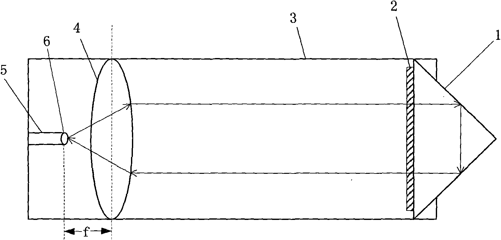
[0032] Such as figure 1 As shown, a reflective optical fiber temperature sensor includes a sapphire sleeve 3, a sapphire isosceles right-angled prism 1 positioned at one end of the sapphire sleeve 3 and a sapphire convex lens 4 positioned at the other end of the sapphire sleeve 3, and the sapphire isosceles right-angled prism 1 The crystal axis orientation of the hypotenuse surface is (0001), and the hypotenuse surface of the sapphire isosceles right-angled prism 1 faces the inner side of the casing 3, and the hypotenuse surface of the sapphire isosceles right-angle prism 1 is coated with ZnO film 2, ZnO film 2 The crystal axis orientation is (0002), and the thickness is about 500nm;

[0033] The other side of the sapphire convex lens 4 relative to the sapphire isosceles rectangular prism 1 is provided with an optical fiber 5 for transmitting light, and the end face 6 of the optical fiber 5 is located at the focal point of the sapphire convex lens 4;

[0034] The optical axis...


PUM


Abstract

The invention discloses a reflection-type optical fiber temperature sensor, which comprises a bushing, a sapphire isosceles right angle triple prism arranged at one end of a bushing and a convex lens arranged at the other end of a bushing. The inclined edge face of the sapphire isosceles right angle triple prism is C axis orientation, faces the inner side of the bushing and is provided with a ZnO thin film. The optical axis of the convex lens is vertical to the inclined edge face of the sapphire isosceles right angle triple prism. The intersection point of the convex lens and the inclined edge face of the sapphire triple prism is approximately located at the inclined edge face center of the sapphire triple prism. The convex lens is provided with optical fibers for transmitting light rays opposite to the other side of the sapphire isosceles right angle triple prism. The end planes of the optical fibers are located at the focus of the convex lens. The temperature measurement range of the optical fiber temperature sensor is 0 to 1800k. The invention has the advantages of simple structure, convenient operation, low cost, wide measurement range and good measurement accuracy and stability.

Description

technical field [0001] The invention relates to the field of optical fiber sensing, in particular to a reflective optical fiber temperature sensor. Background technique [0002] Optical fiber temperature sensors have broad application prospects in industrial production, aerospace and other fields. Its probe and instrument are separated, and optical fiber is used as the optical path, which can perform non-contact, non-destructive and long-distance measurement in harsh environments, which increases the environmental adaptability of the sensor and takes advantage of the advantages of optical fiber itself, such as long distance Low loss, easy to bend, small size, light weight, low cost, waterproof, fireproof, corrosion resistance, anti-electromagnetic interference, etc. At the same time, it is also easy to connect with a computer to realize intelligent and long-distance monitoring. In many cases, it can complete tasks that are difficult or even impossible for traditional sensor...

Claims


Application Information

Patent Timeline
IPC IPC(8): G01K11/32G02B5/04G02B7/02
Inventor 隋成华夏娟刘玉玲徐天宁
Owner ZHEJIANG UNIV OF TECH
Features
  • R&D
  • Intellectual Property
  • Life Sciences
  • Materials
  • Tech Scout
  • Unparalleled Data Quality
  • Higher Quality Content
  • 60% Fewer Hallucinations
Learn More