Supercharge Your Innovation With Domain-Expert AI Agents!

Girdle photon sieve and manufacturing method thereof

A technology of photon sieve and annular zone, applied in optics, optical components, microlithography exposure equipment, etc., can solve the problem that the far-field main lobe is not small enough

Active Publication Date: 2010-11-10
INST OF MICROELECTRONICS CHINESE ACAD OF SCI
View PDF0 Cites 12 Cited by
  • Summary
  • Abstract
  • Description
  • Claims
  • Application Information

AI Technical Summary

Problems solved by technology

[0013] However, due to the fact that the far-field main lobe produced by the photon sieve is still not small enough

Method used


Image

  • Girdle photon sieve and manufacturing method thereof
  • Girdle photon sieve and manufacturing method thereof
  • Girdle photon sieve and manufacturing method thereof

Examples


Embodiment Construction

[0037] In order to make the object, technical solution and advantages of the present invention clearer, the present invention will be described in further detail below in conjunction with specific embodiments and with reference to the accompanying drawings.

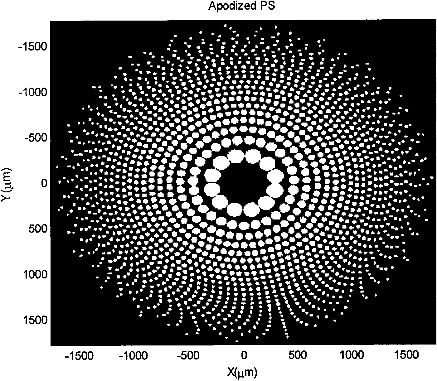
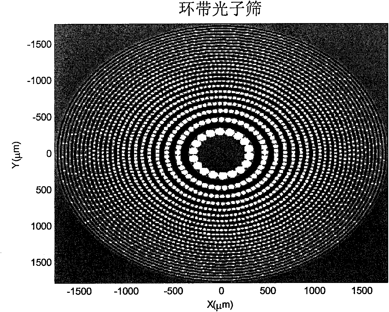
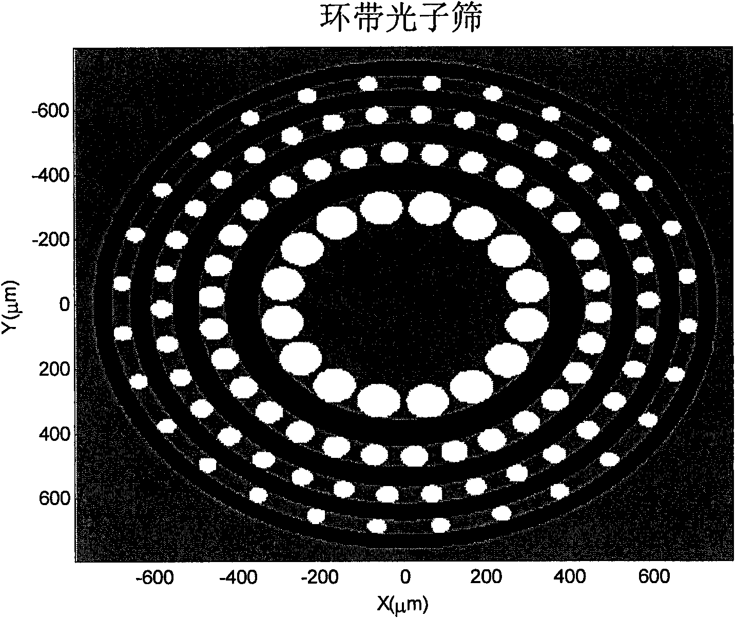
[0038]Ring photon sieve is a new type of diffractive optical phase element, that is, phase plate. The phase plate is placed before or after the diffraction-limited lens, and corrects the light intensity of each spectrum of the far-field diffraction spot of the laser beam to achieve a diffraction center diffraction spot with more concentrated energy than the diffraction center spot of an ordinary photon sieve. The phase plate (annular photon sieve) of the present invention adopts a smaller diffraction circular hole and an etched diffraction ring structure with a phase of π to replace the single-circle diffraction aperture of an ordinary photon sieve. The position and number of diffraction units are consistent with ordinary...


PUM

PropertyMeasurementUnit
Thicknessaaaaaaaaaa

Abstract

The invention discloses a girdle photon sieve which is formed by alternately nesting a plurality of concentric diffracting holes and a plurality of concentric etching annular girdles. A diffracting hole girdle is most close to the center of the girdle photon sieve; the widths of the diffracting hole girdle and an etching annular girdle respectively decrease gradually from the center of the girdlephoton sieve to the outside; the width of the diffracting hole girdle is the same with the width of the adjacent etching annular girdle in the direction far away from the center of the girdle photon sieve; thus the odd girdles and the even girdles of a wave zone plate are both provided with transmitting parts which are respectively the light holes of the odd girdles and the etching phase girdles of the even girdles, or the light holes of the even girdles and the etching phase girdles of the odd girdles; the size of each light hole is the same with the width of the corresponding girdle. The invention also discloses a method for manufacturing the girdle photon sieve. By the invention, focusing diffraction light intensity of the photon sieve is improved, that is to say, the energy of the main spot of far field diffraction spots of a laser beam is increased.

Description

technical field [0001] The invention belongs to the technical field of wavefront shaping of laser beams, in particular to an annular photon sieve and a manufacturing method thereof for realizing energy enhancement of a main spot of a laser beam in a far-field diffraction spot. The photon sieve can be used in beam shaping, microelectronics maskless etching, intense laser energy concentration and other various instruments that require energy to be focused to the central spot. Background technique [0002] At present, extremely small main spot width and extremely high main spot energy are required in beam shaping, microelectronic maskless etching, intense laser energy concentration and other instruments that require energy to be focused to the central spot. Therefore, it is a practical subject to increase the energy of the main spot of the laser diffraction spot and suppress the energy of the side spots through various approaches. [0003] The compression of the central main s...

Claims


Application Information

Patent Timeline
IPC IPC(8): G02B5/00G02B27/42G02B27/09G03F7/20
Inventor 贾佳谢常青刘明
Owner INST OF MICROELECTRONICS CHINESE ACAD OF SCI
Features
  • R&D
  • Intellectual Property
  • Life Sciences
  • Materials
  • Tech Scout
  • Unparalleled Data Quality
  • Higher Quality Content
  • 60% Fewer Hallucinations
Learn More