Differential signaling serial interface circuit

A serial interface, differential signal technology, applied in the direction of logic circuit connection/interface layout, electrical components, baseband system, etc., can solve the problem of signal stability recovery failure, unable to maintain the initial value, circuit reliability deterioration and other problems

Inactive Publication Date: 2010-11-10
DONGBU HITEK CO LTD
View PDF4 Cites 9 Cited by
  • Summary
  • Abstract
  • Description
  • Claims
  • Application Information

AI Technical Summary

Problems solved by technology

Thus, the voltage V applied to the voltage comparator of the column drive receiver DIFF Due to having I D *R T Therefore, the initial value cannot be maintained, but it is attenuated in proportion to the impedance added to the signal line pattern, which in turn causes the failure of the stable recovery of the signal, which leads to the problem that the reliability of the entire circuit deteriorates

Method used


Image

  • Differential signaling serial interface circuit
  • Differential signaling serial interface circuit
  • Differential signaling serial interface circuit

Examples


Embodiment Construction

[0021] Reference will now be made in detail to specific embodiments of the present invention, which are shown in the accompanying drawings. Wherever possible, the same reference numerals will be used in all figures to indicate the same or similar parts.

[0022] The system and operation of the present invention shown in the drawings and described with reference to the drawings is a description of at least one embodiment, but the description neither limits the technical aspects nor the essential system and operation.

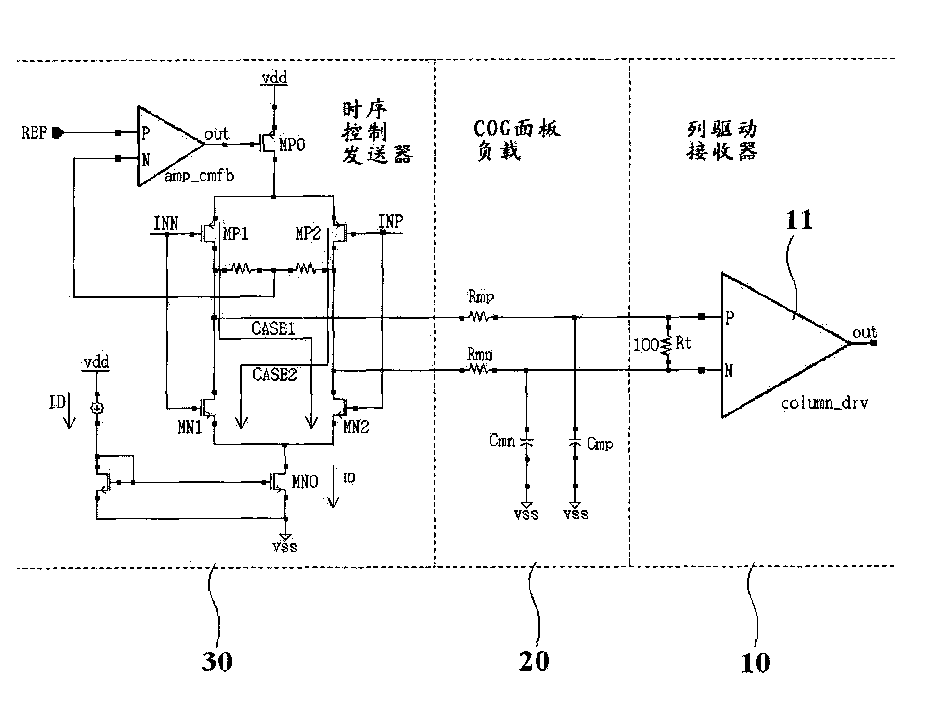
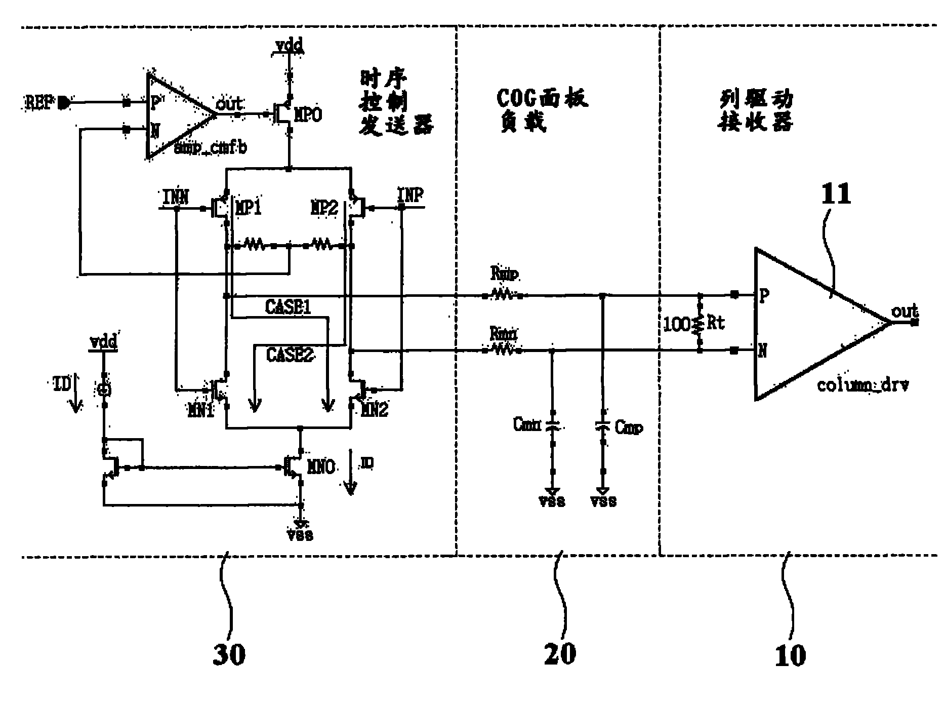
[0023] figure 2 The push-pull differential signal serial interface circuit according to the preferred embodiment of the present invention is shown.

[0024] Reference figure 2 , The circuit includes a column driver receiver 10 provided with a voltage comparator 11, and a terminal resistor R connected to the two input terminals P and N of the voltage comparator T . This circuit has an end resistor R embedded in the column driver receiver 10 T . Specifically, the en...


PUM


Abstract

The invention relates to a semiconductor circuit, in particular to a push-pull type differential signaling serial interface circuit. The differential signaling serial interface circuit includes a receiver including a voltage comparator having input terminals with a termination resistor RT, a panel in front of the receiver, the panel having a load, and a transmitter for supplying a differential input current to the load of the panel.

Description

[0001] Cross reference to related applications [0002] This application claims the priority of Korean Patent Application No. 10-2008-0137605 filed on December 30, 2008, the entire content of which is incorporated herein by reference. Technical field [0003] The present invention relates to a semiconductor circuit, and more specifically, to a push-pull type differential signal serial interface circuit. Background technique [0004] figure 1 The prior art push-pull differential signal serial interface circuit is shown. [0005] reference figure 1 In the case of a general TFT-LCD, the output drive current I from the TCON transmitter D It is converted into voltage I in the PCB with the timing controller D *R T (=V DIFF ). [0006] The converted voltage V DIFF It is applied to the voltage comparator in the column driver receiver packaged by COF (Chip OnFilm). Then, the column driver receiver detects the voltage V DIFF The difference and restore a signal. In this case, the voltage V ...

Claims


Application Information

Patent Timeline
Patent Type & Authority Applications(China)
IPC IPC(8): G09G3/36G09G3/20
CPCH04L25/0298G09G3/3688G09G2300/0426H04L25/0272H03K19/0175H04L25/02
Inventor 朴旭熙尹永彬
Owner DONGBU HITEK CO LTD
Why Eureka
Try Eureka