Motor rotor of permanent-magnetic synchronous tractor

A motor rotor and permanent magnet synchronous technology, applied in the direction of magnetic circuit rotating parts, manufacturing stator/rotor body, magnetic circuit shape/style/structure, etc., can solve the complicated processing of magnetic steel end plate, complex manufacturing process, positioning Poor precision and other problems, to achieve the effect of optimizing the fixing method, flexible and convenient installation, and easy processing

Inactive Publication Date: 2010-11-10
宁波华夏一品电梯有限公司
View PDF7 Cites 3 Cited by
  • Summary
  • Abstract
  • Description
  • Claims
  • Application Information

AI Technical Summary

Problems solved by technology

Although this technical solution can fix the magnetic steel, there are many parts and the manufacturing process is complicated
Another example is the utility model patent ZL200520098758.X which discloses a permanent magnet rotor, which uses a retainer to fix the magnetic steel. This technical solution has defects such as poor positioning accuracy and failure of the retainer.
Another example is the utility model patent ZL02248618.6 which discloses "a permanent magnet rotor". The edge of the side of the magnetic steel end plate is provided with flanges uniformly distributed in the circumferential direction, and the magnetic steel is fixed by adjacent flanges. This technology The disadvantage of the scheme is that the processing of the magnetic steel end plate with flange is complicated and the cost is high

Method used


Image

  • Motor rotor of permanent-magnetic synchronous tractor
  • Motor rotor of permanent-magnetic synchronous tractor
  • Motor rotor of permanent-magnetic synchronous tractor

Examples


Embodiment Construction

[0025] The following are specific embodiments of the present invention, and further describe the technical solution of the present invention in conjunction with the accompanying drawings, but the present invention is not limited to these embodiments.

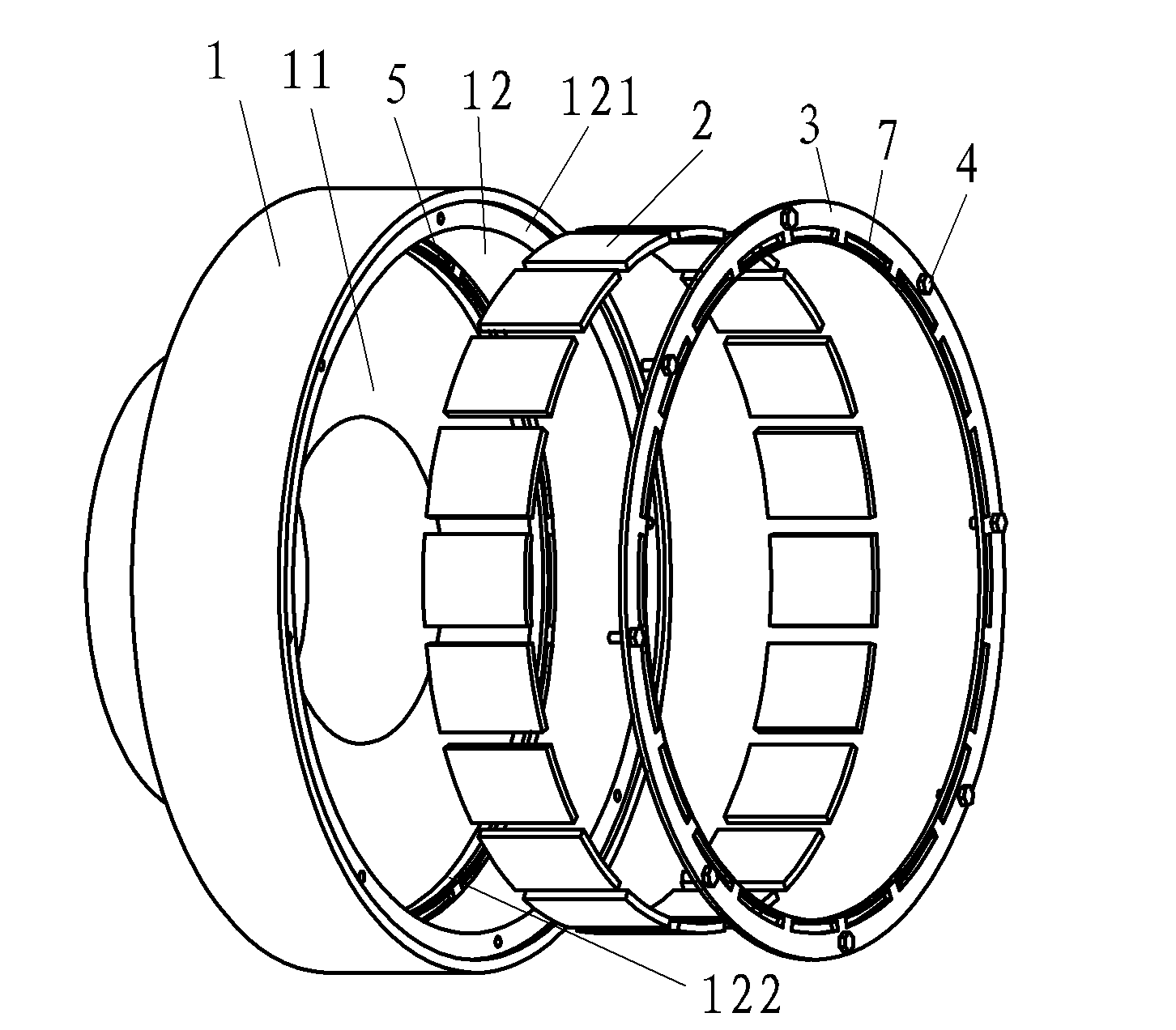
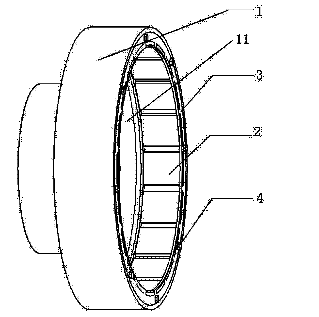
[0026] Such as figure 1 As shown, the motor rotor of the permanent magnet synchronous traction machine includes the rotor body 1, the magnetic steel 2, the outer magnetic steel end plate 3, the inner magnetic steel end plate 5 and the bolt 4, through the magnetic steel end plate 3 and the bolt 4, the The magnetic steel 2 is fixed on the rotor body 1 so that the magnetic steel can be kept from falling off even when the adhesive fails.

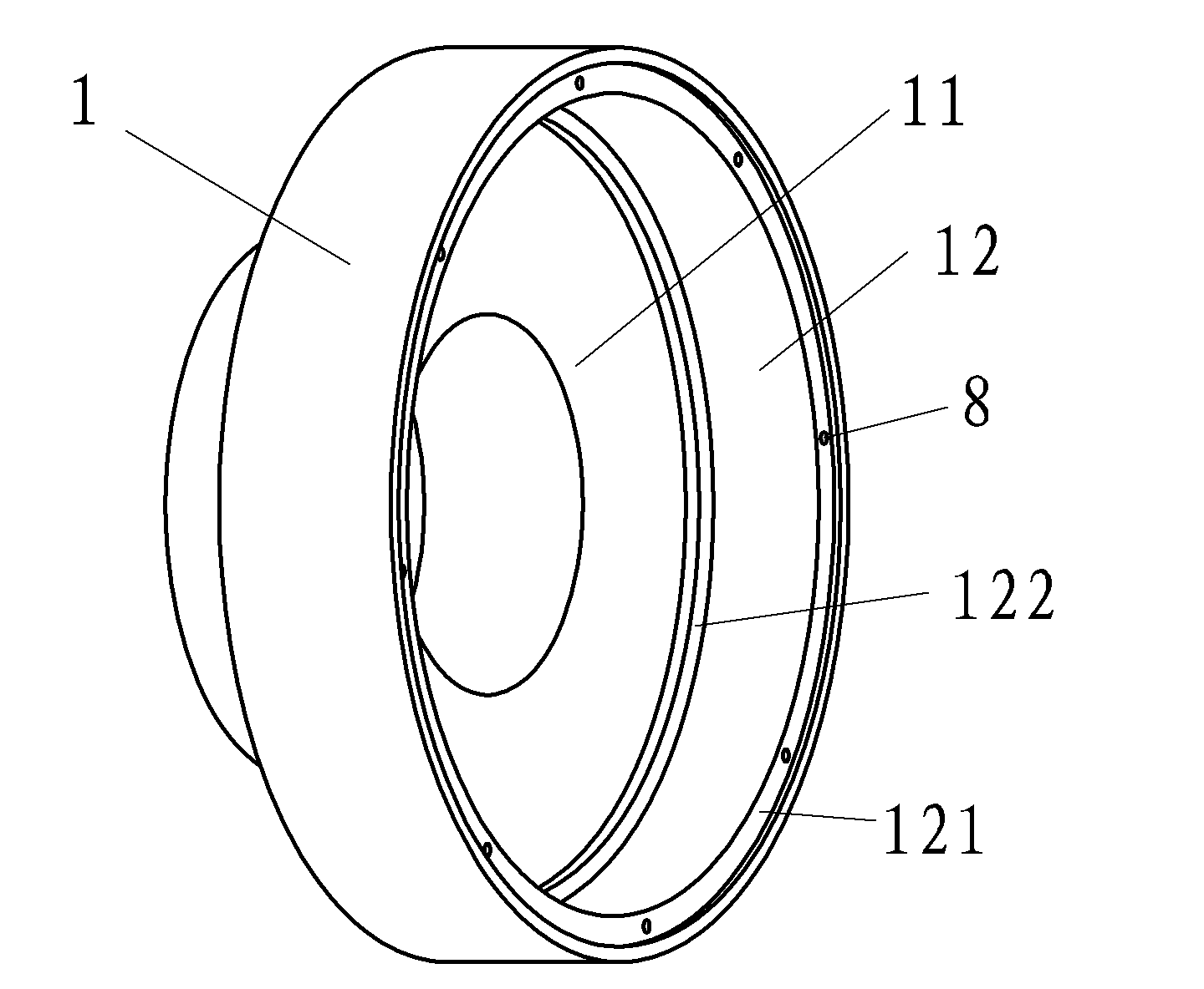
[0027] Specifically, image 3 It is the rotor body 1 of the present invention, and its inner cavity is composed of a stepped bottom surface 11 and an annular inner wall 12. An annular step 121 is arranged on the outer end surface of the annular inner wall 12. There are bolt holes 6 on the plane o...


PUM


Abstract

The invention provides a motor rotor of a permanent-magnetic synchronous tractor, which belongs to the technical field of elevators and solves the problem that the magnetic steels of the conventional motor rotor are easy to drop. The motor rotor of the permanent-magnetic synchronous tractor comprises a rotor body with a step-shaped bottom surface and an annular inner wall, wherein a plurality of uniformly distributed magnetic steels are stuck on the annular inner wall of the rotor body. The motor rotor is characterized in that: two ends of the magnetic steels are provided with an inner magnetic steel end plate and an outer magnetic steel end plate which are of annular sheets and are fixed on the rotor body respectively, the inner and outer magnetic steel end plates are provided with positioning parts with the same magnetic steel number and position, and the two ends of the magnetic steels are inserted into the corresponding positioning parts. The motor rotor can simplify the fixed structures of the magnetic steels and reduce the cost, and the magnetic steels can be firmly and fixedly connected on the motor rotor and do not drop.

Description

technical field [0001] The invention belongs to the technical field of motors, and relates to a motor rotor of a permanent magnet synchronous traction machine, in particular to a fixing method of magnetic steel in the motor rotor. Background technique [0002] The permanent magnet synchronous traction machine is more and more widely used, and gradually becomes the mainstream type of traction machine. Due to better technology and better performance, the motor rotors of permanent magnet synchronous traction machines use surface-mounted magnets or semi-buried magnets, and for this type of motor rotors, adhesives are generally used to attach the magnets fixed on the motor rotor. However, due to the heating of the motor and the impact of the tangential force of the motor, the adhesive will age and lose its effect after long-term operation, and the magnetic steel will often fall off, which will have a great impact on the stable operation of the traction machine motor. It may eve...

Claims


Application Information

Patent Timeline
Patent Type & Authority Applications(China)
IPC IPC(8): H02K1/27H02K15/03
Inventor 刘行王伟峰
Owner 宁波华夏一品电梯有限公司
Why Eureka
Try Eureka