Dual-substrate triangular arc support-blade asymmetrically-combined rotary flexible shaft supporting tube

An asymmetric and support tube technology, applied in the direction of flexible shafts, shafts, shafts and bearings, can solve the problems of unsatisfactory improvement effects, achieve the effects of preventing rotation, simple replacement, and cost reduction

Inactive Publication Date: 2010-11-17
宋健
View PDF7 Cites 1 Cited by
  • Summary
  • Abstract
  • Description
  • Claims
  • Application Information

AI Technical Summary

Problems solved by technology

However, when these types of rotating flexible shaft support tubes are used on plant protection machinery with arc-shaped bending at the front end of the metal outer sleeve, the improvement effect of wear, vibration and noise is not ideal.

Method used


Image

  • Dual-substrate triangular arc support-blade asymmetrically-combined rotary flexible shaft supporting tube
  • Dual-substrate triangular arc support-blade asymmetrically-combined rotary flexible shaft supporting tube
  • Dual-substrate triangular arc support-blade asymmetrically-combined rotary flexible shaft supporting tube

Examples


Embodiment 1

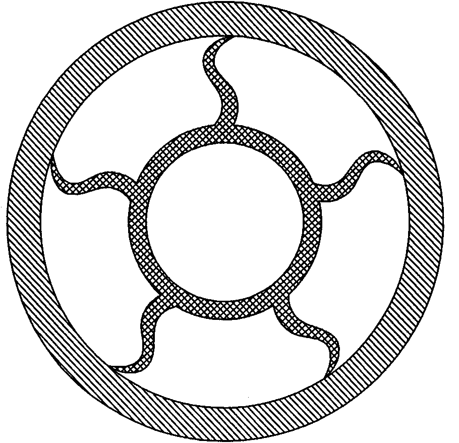
[0024] Embodiment 1: In the cross-section of the inner tube body 1, the line connecting the tip apex of the elastic support blade 3 and the center of the ring where the inner tube body 1 is located passes through the corresponding left lobe 3.1 of the elastic support blade 3 and the blade The outer wall surface of the inner tubular body 1 between the right lobe 3.2, such as Figure 4 .

Embodiment 2

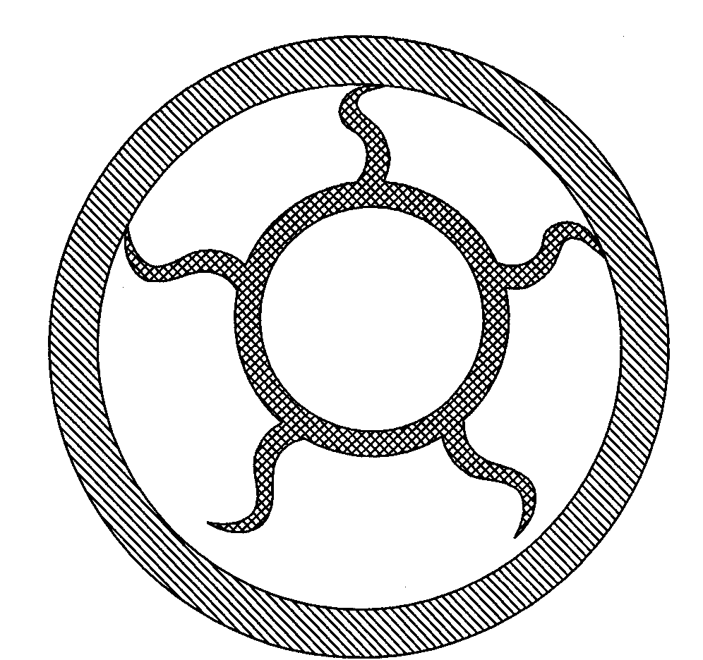
[0025] Embodiment 2: In the cross-section of the inner tube body 1, the line connecting the tip apex of the elastic support blade 3 and the center of the ring where the inner tube body 1 is located passes through the outer wall surface of the inner tube body 1 on the outside of the elastic support blade 3 ,Such as Figure 5 .

[0026] The section of the rigid support blade 2 is a solid rectangle.

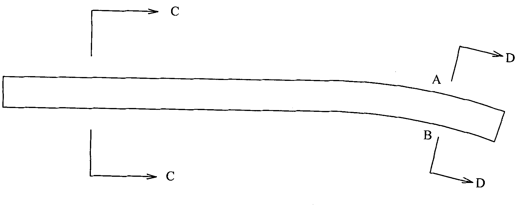
[0027] The thickness of the rigid support blade 2 from the root to the blade tip is consistent to increase the mechanical strength of the blade itself. The direction of the action and reaction force between the rigid support blade 2 and the metal outer sleeve is radially consistent, without tangential component force, and is not easy to bend and deform . At the outer arc part of the bending of the metal outer sleeve, that is, the A position, the radial reaction force on the rigid support blade 2 formed by the rebound stress after the bending of the support tube presses the inner w...


PUM


Abstract

The invention relates to a dual-substrate triangular arc support-blade asymmetrically-combined rotary flexible shaft supporting tube, comprising an inner tube, elastic support blades and rigid support blades, wherein the elastic support blades and the rigid support blades are fixedly on and integrated with the outer surface of the inner tube, the distance between the top of the elastic support blades and the tube core of the inner tube is the same with the distance between the top of the rigid support blades and the tube core of the inner tube, the rigid support blades are arranged on the outer surface of the inner tube corresponding to the central angle of the inner tube less than or equal to 180 degree, the total number of the elastic support blades and the rigid support blades is 3-8, a cambered blade left petal and a cambered blade right petal form one elastic support blade, the bottom of the blade left petal and the bottom of the blade right petal are fixed on the outer wall of the inner tube, the top of the blade left petal and the top of the blade right petal are integrated into a whole, and the blade left petal, the blade right petal and the outer wall of the inner tube form a curved-edge triangle cavity. The invention has the advantages of no following rotation phenomenon, small vibration and greatly prolonged service life, and prevents the inner tube and the rotary flexible shaft from being stuck.

Description

technical field [0001] The invention relates to a rotating flexible shaft support tube with asymmetric combination of double-substrate triangular arc-shaped support blades. Background technique [0002] In the lawn mowers and scarifiers of plant protection machinery, the support tube must be used to support the rotating flexible shaft. When in use, the support tube is inserted into the metal outer tube, and the rotating flexible shaft transmits power to the working cutter head to perform operations. In the past, a general support tube was mainly composed of an inner tube body and support blades fixedly arranged on the outer wall of the inner tube body. The radial directions of the support blades and the inner tube body were consistent, and the thickness of the top and bottom ends of the support blades was uniform. During installation, in order to ensure the stable insertion of the support blades in the metal outer tube, the distance between the outer end of the support blade...

Claims


Application Information

Patent Timeline
IPC IPC(8): F16C1/26
Inventor 宋健
Owner 宋健
Why Eureka
Try Eureka