Machine room heat removal device for evaporation cooling type heat-pipe heat exchange

A heat pipe heat exchange and evaporative cooling technology, used in household heating, heating methods, household heating and other directions, to achieve the effect of reducing the start-up temperature difference, uniform temperature difference, and good energy saving

Active Publication Date: 2010-11-17
TSINGHUA UNIV
View PDF9 Cites 24 Cited by
  • Summary
  • Abstract
  • Description
  • Claims
  • Application Information

AI Technical Summary

Problems solved by technology

However, in the above patents, the heat pipe directly uses the outdoor air for coolin

Method used


Image

  • Machine room heat removal device for evaporation cooling type heat-pipe heat exchange
  • Machine room heat removal device for evaporation cooling type heat-pipe heat exchange
  • Machine room heat removal device for evaporation cooling type heat-pipe heat exchange

Examples


Embodiment 1

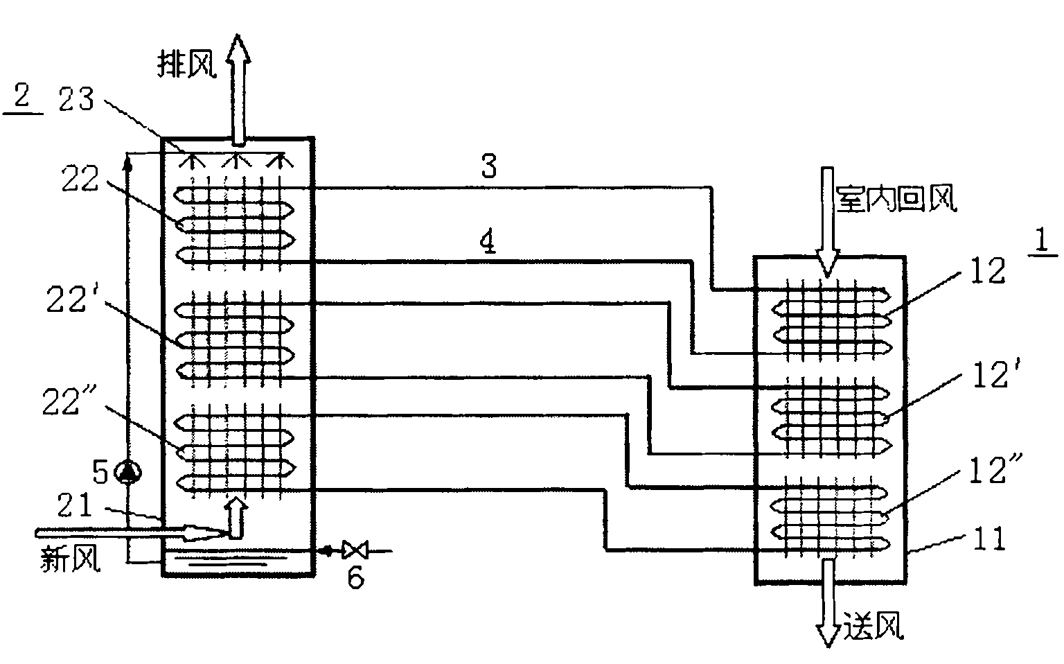
[0017] Such as figure 1 As shown, the heat removal device of this embodiment includes an evaporator 1 installed in the machine room, a water-cooled condenser 2 installed outside the machine room, a gas main pipe 3 and a liquid main pipe 4 . The evaporator 1 includes a box body 11 and three sets of evaporation side heat pipes 12 arranged in the box body; the water-cooled condenser 2 includes a box body 21, three groups of condensation side heat pipes 22 arranged in the box body 21 and a set The spray device 23 on the top of the body 21, and the spray device 23 communicates with the bottom of the box body 21 through a water pump 5 to form a cooling water circulation loop. The outlets of each group of evaporating side heat pipes 12 communicate with the inlets of the corresponding condensing side heat pipes 22 through a gas main pipe 3 respectively, and the outlets of each group of condensing side heat pipes 22 respectively pass through a liquid main pipe 4 and the corresponding e...

Embodiment 2

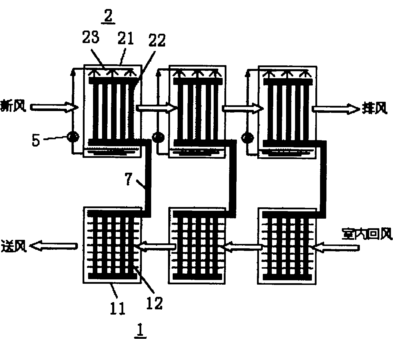
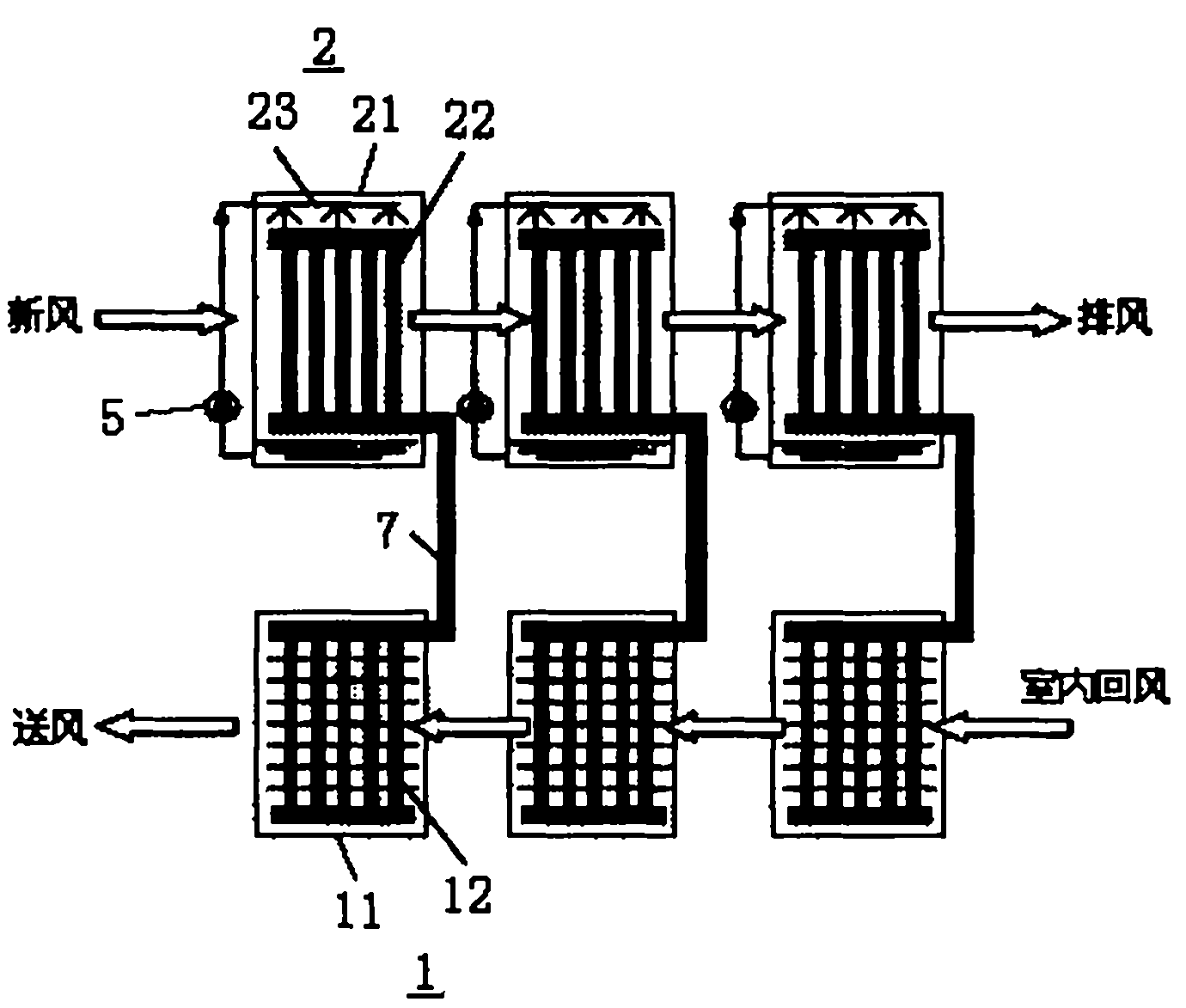
[0025] Such as figure 2 As shown, the difference between this embodiment and Embodiment 1 is: (1) the bottom of each group of condensation-side heat pipes 22 communicates with the top of the corresponding evaporation-side heat pipes 12 through a gas-liquid main pipe 7, which is simpler in structure; (2) The outdoor water-cooled condenser 2 is an independent water circulation loop. In Embodiment 1, the water-cooled condenser 2 is a unified water circulation loop. When the circulating water volume is relatively small, it cannot ensure that the fins of the heat pipe 22 on the condensation side are fully wetted; when the circulating water volume is too large, each stage of condensation The temperature change of the side heat pipes 22 is relatively small, so that the temperature difference of the refrigerant in each group of condensing side heat pipes 22 is relatively small, resulting in a limited cooling range of the indoor air. This embodiment can avoid the double influence of ...


PUM


Abstract

The invention relates to a machine room heat removal device for evaporation cooling type heat-pipe heat exchange. The device is characterized by comprising more than one group of evaporators arranged in a machine room, more than one group of water-cooled condensers arranged outside the machine room and more than one gas-liquid main pipe, wherein each group of evaporators comprises an evaporation tank body and an evaporation side heat pipe arranged in the evaporation tank body; each group of water-cooled condensers comprises a condensation tank body, a condensation side heat pipe arranged in the condensation tank body and a spray device arranged on the top of the condensation tank body; a cooling water circulating loop is formed by communicating the spray device and the bottom of the condensation tank body through a water pump; the top of each group of evaporation side heat pipe is communicated with the bottom of the corresponding condensation side heat pipe through one gas-liquid main pipe; and the evaporation side heat pipe and the condensation side heat pipe are filled with a refrigerating medium. The device ensures more uniform temperature difference between the groups of heat pipes during the heat transfer, has an overall heat exchange efficiency close to one and air supply temperature close to the wet bulb temperature of outdoor air, can reduce the starting temperature difference between indoor temperature and outdoor temperature and further increase the service time of the heat pipe to achieve better energy saving effect.

Description

technical field [0001] The invention relates to heat exchange equipment, in particular to an evaporative cooling type heat pipe heat exchange machine room heat exhaust device, which belongs to the technical field of heat exchange equipment. Background technique [0002] Today, with the rapid development of communication technology and computer technology, the number and scale of base stations as information transmission hubs and computer rooms as data processing centers are also increasing. The indoor heat generation in such places is very large, generally 300-1000W / m 2 , The power consumption of the air-conditioning system accounts for about 40% of the energy consumption of the entire computer room, which has great energy-saving potential. Heat pipes are a type of air-conditioning system that can efficiently utilize outdoor cold sources to remove heat from buildings. Generally, they can be activated when the temperature difference between indoor and outdoor is above 5°C, w...

Claims


Application Information

Patent Timeline
IPC IPC(8): F24F5/00F24F13/30
Inventor 李震刘晓华
Owner TSINGHUA UNIV
Why Eureka
Try Eureka