Bending type parallel flow heat exchanger

A parallel flow heat exchanger and parallel flow technology, applied in the direction of heat exchanger types, indirect heat exchangers, heat exchange equipment, etc., can solve the problem that the heat transfer coefficient of the heat exchanger cannot meet the ideal requirements and the heat transfer temperature difference is large , heat transfer coefficient is not high, etc., to achieve the effect of uniform temperature difference, increase heat transfer efficiency, and improve overall performance

Inactive Publication Date: 2021-06-29
江苏晨宇科技有限公司
View PDF6 Cites 0 Cited by
  • Summary
  • Abstract
  • Description
  • Claims
  • Application Information

AI Technical Summary

Problems solved by technology

This type of heat transfer type has a large heat transfer temperature difference and a low heat transfer coefficient, which leads to the fact that the heat transfer coefficient of the entire heat exchanger cannot meet the ideal requirements.

Method used


Image

  • Bending type parallel flow heat exchanger
  • Bending type parallel flow heat exchanger
  • Bending type parallel flow heat exchanger

Examples


Embodiment 1

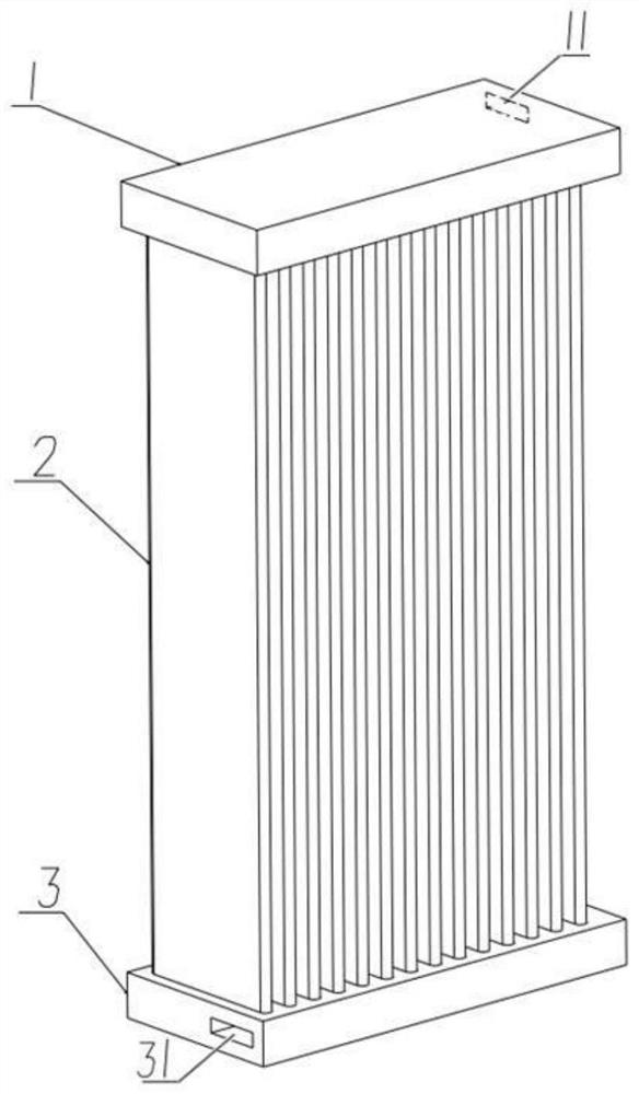
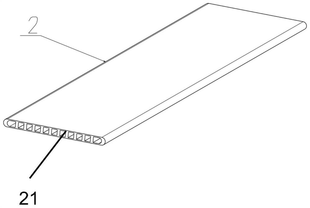
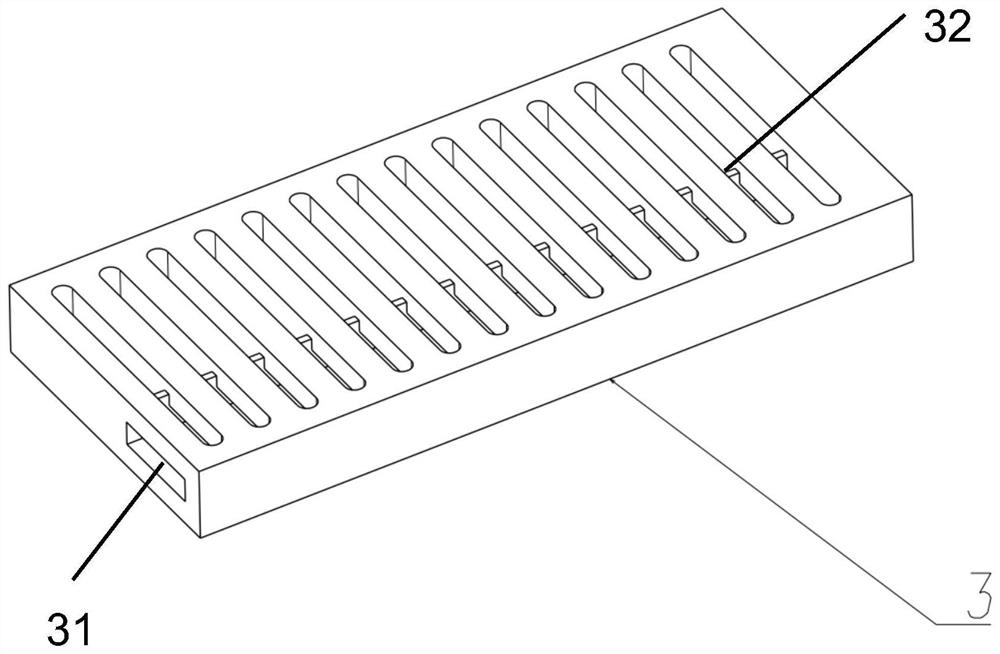
[0018] Such as figure 1 As shown, a bent parallel flow heat exchanger includes an upper end plate 1 and a lower end plate 3, a plurality of parallel flat tubes 2 are fixed between the upper end plate 1 and the lower end plate 3, and a plurality of flat tubes 2 are arranged inside the flat tubes 2. Parallel parallel flow channels 21, the upper end plate 1 is provided with a refrigerant inlet 11 and an upper drainage groove (not shown in the figure), and the lower end plate 3 is provided with a refrigerant outlet 31 and a lower drainage groove 32, and the refrigerant passes through the upper end plate The refrigerant inlet 11 of 1 enters the upper drainage groove, flows into the flat tube 2, passes through the parallel flow channel 21 in the flat tube 2, reaches the lower drainage groove 32 at the lower end plate 3, and then enters the flat tube 2 and flows into the upper end plate 1 to reach the upper end The upper drainage groove of the plate 1 changes direction and then enter...

Embodiment 2

[0022] Such as Figure 6 , a bent parallel flow heat exchanger, comprising an upper end plate 1 and a lower end plate 3, a plurality of flat tubes 2 arranged in parallel are fixed between the upper end plate 1 and the lower end plate 3, and S-shaped flow channels are arranged in the flat tubes 2 21. The lower end of the flat tube 2 is provided with a refrigerant inlet pipe 5, and the upper end of the flat pipe 2 is provided with a refrigerant outlet pipe 4. Both the refrigerant inlet pipe 5 and the refrigerant outlet pipe 4 are provided with a plurality of square holes 6, and the refrigerant inlet Each square hole 6 on the tube 5 corresponds to the refrigerant inlet 23 on each flat tube 2 , and each square hole 6 on the refrigerant outlet pipe 4 corresponds to the refrigerant outlet 23 on each flat tube 2 .

[0023] The upper end plate 1 and the lower end plate 3 of the heat exchanger play the role of installing and fixing the flat tube 2; the flow channel type in the flat tub...


PUM


Abstract

The invention discloses a bending type parallel flow heat exchanger, which comprises an upper end plate and a lower end plate; a plurality of parallel flat pipes are fixed between the upper end plate and the lower end plate; a plurality of parallel flow channels are arranged in the flat pipes; a refrigerant inlet and an upper drainage groove are arranged in the upper end plate, and a refrigerant outlet and a lower drainage groove are arranged in the lower end plate; and a refrigerant enters the upper drainage groove through the refrigerant inlet of the upper end plate, flows into the flat pipes, reaches the lower drainage groove in the lower end plate through the parallel flow channels in the flat pipes, then enters the flat pipes, flows to the upper end plate, reaches the upper drainage groove in the upper end plate, changes the direction, then enters the flat pipes, reaches the lower end plate and finally flows out of the refrigerant outlet of the lower end plate. The S-shaped parallel flow heat exchanger of the invention can replace a traditional parallel flow heat exchanger, the temperature difference between gas and the heat exchanger in the gas heat exchange process is more uniform, the overall performance of the heat exchanger can be effectively improved, and the heat exchange efficiency of the heat exchanger is greatly improved.

Description

technical field [0001] The invention relates to a heat exchanger. Background technique [0002] Existing parallel flow heat exchangers are generally of a parallel parallel structure. This type of heat transfer type has a large heat transfer temperature difference and a low heat transfer coefficient, which leads to the fact that the heat transfer coefficient of the entire heat exchanger cannot meet the ideal requirements. Contents of the invention [0003] The purpose of the present invention is to overcome the deficiencies in the prior art, and provide a bending type parallel flow heat exchange, which can not only make the heat exchange temperature difference more uniform, but also improve the heat exchange coefficient. [0004] The technical scheme provided by the invention is: [0005] A bent parallel flow heat exchanger, comprising an upper end plate and a lower end plate, a plurality of parallel flat tubes are fixed between the upper end plate and the lower end plate...

Claims


Application Information

Patent Timeline
Patent Type & Authority Applications(China)
IPC IPC(8): F28D1/053F28F1/02
CPCF28D1/05358F28F1/022
Inventor 张亚军
Owner 江苏晨宇科技有限公司
Why Eureka
Try Eureka