Differential frequency multiplication rotary coder

A rotary encoder and differential technology, applied in the field of differential frequency multiplication rotary encoder, can solve the problems of high ambient temperature, no good ground wire, large vibration of the transmission drum and transmission mechanism, etc., and achieve high-precision measurement and direction identification and debugging. The effect of easy and simple calibration and long data transmission distance

Inactive Publication Date: 2010-11-17
JINAN WISDOM INTELLIGENT TECH
View PDF8 Cites 2 Cited by
  • Summary
  • Abstract
  • Description
  • Claims
  • Application Information

AI Technical Summary

Problems solved by technology

However, the working environment of construction machinery equipment and lifting equipment is harsh and complex, the driving drum and the transmission mechanism vibrate greatly, the ambient temperature is high, the cable is long, and there is no good ground wire, the interference is very strong, especially in the frequency conversion application mechanism

Method used


Image

  • Differential frequency multiplication rotary coder
  • Differential frequency multiplication rotary coder
  • Differential frequency multiplication rotary coder

Examples


Embodiment Construction

[0017] The present invention will be further described below in conjunction with the accompanying drawings and embodiments.

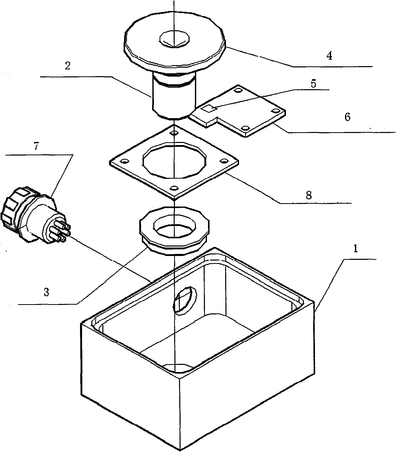
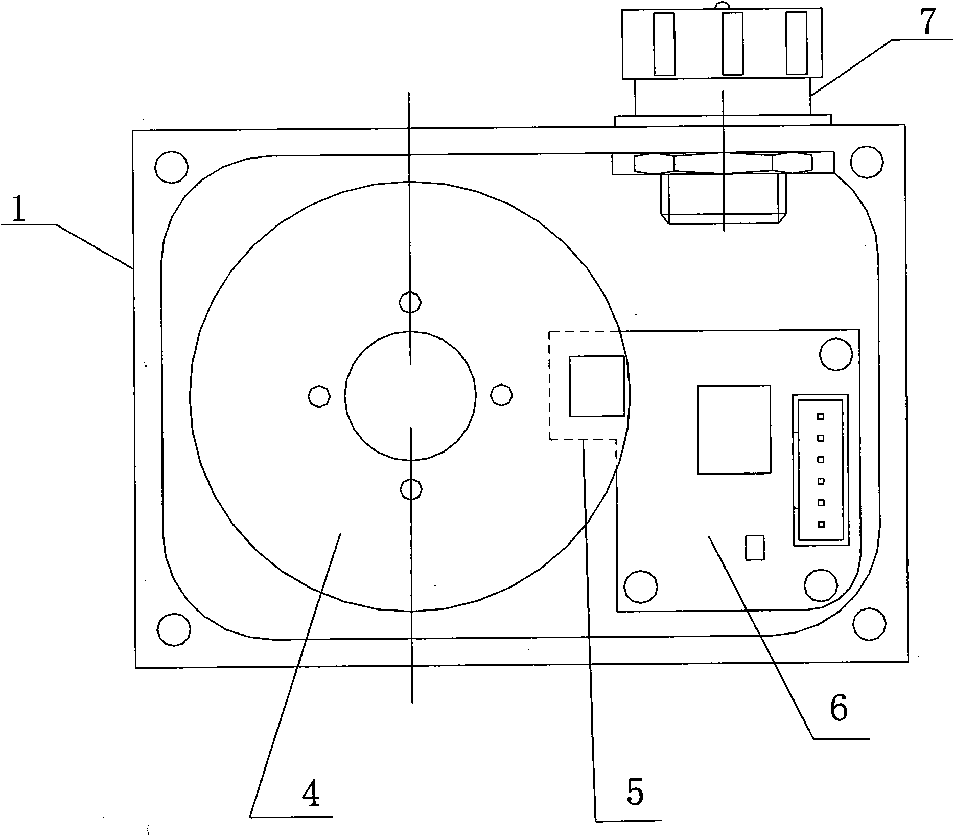
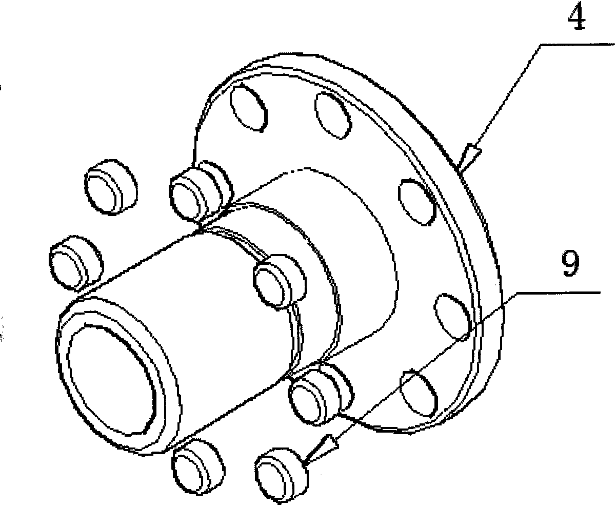
[0018] figure 1 , figure 2 , image 3 It includes a housing 1, the housing 1 is provided with a connecting shaft 2, one end of the connecting shaft 2 is installed in the bearing 3, and the other end is connected with the pulse code disc 4; the housing 1 is also provided with a dual-channel Hall The chip 5 and the differential conditioning circuit 6 are connected to the aviation plug 7, and the dual-channel Hall chip 5 corresponds to the pulse code disc 4. The connecting shaft 2 is connected with the bearing 3 through the bearing fixing piece 8 . Several magnetic steels 9 are evenly distributed on the circumference of the pulse code disc 4 .


PUM


Abstract

The invention relates to a differential frequency multiplication rotary coder which has the advantages of simple structure, convenient use, long service life, strong interference resistance, stable performance, and the like. The differential frequency multiplication rotary coder structurally comprises a shell, wherein a connecting shaft is arranged in the shell; one end of the connecting shaft is installed in a bearing, and the other end is connected with a pulse code disk; a double-channel Hall chip and a differential conditioning circuit are also arranged in the shell; and the circuit is connected with an aviation plug, and the double-channel Hall chip corresponds to the pulse code disk.

Description

technical field [0001] The invention relates to a differential frequency multiplication rotary encoder used for distance detection and direction identification of construction machinery and hoisting equipment. Background technique [0002] In the field of construction machinery, existing sensing technologies mostly use potentiometers and encoders to detect distances. The potentiometer method mainly uses a mechanical stroke limiter plus a potentiometer for measurement. The rotation of the worm drives the rotation of the potentiometer, so that the voltage changes. Calculate the distance of each mechanism according to the voltage for limit control. In practical applications, this technology has some problems that must be solved. The mechanical worm gear itself has processing errors, and the potentiometer is a contact type, which cannot rotate freely for multiple turns and has a certain service life. Therefore, this method of distance measurement The precision is not enough. ...

Claims


Application Information

Patent Timeline
Patent Type & Authority Applications(China)
IPC IPC(8): G01D5/249G01D3/028
Inventor 候宇明徐金钊娄天纲
Owner JINAN WISDOM INTELLIGENT TECH
Why Eureka
Try Eureka