Chip tester and test method thereof

A tester and chip technology, applied in the field of tester, can solve problems such as insufficient ink remaining in the ink cartridge, inconvenient use, failure to detect the normal operation of piezoelectric sensors or similar components, etc., and achieve the effect of reducing defective products

Inactive Publication Date: 2010-11-17
ZHUHAI TIANWEI TECH DEV CO LTD
View PDF10 Cites 21 Cited by
  • Summary
  • Abstract
  • Description
  • Claims
  • Application Information

AI Technical Summary

Problems solved by technology

[0010] However, the existing chip tester is only equipped with a detection unit for judging whether the electronic module is correctly written in data, and cannot detect whether the piezoelectric sensor or similar components are working normally. Once the ink cartridge with a defective piezoelectric sensor is installed in the inkjet printer On the contrary, the inkjet printer will think that the ink in the ink cartridge is insufficient and cannot work, which will bring great inconvenience to the user

Method used


Image

  • Chip tester and test method thereof
  • Chip tester and test method thereof
  • Chip tester and test method thereof

Examples


Embodiment Construction

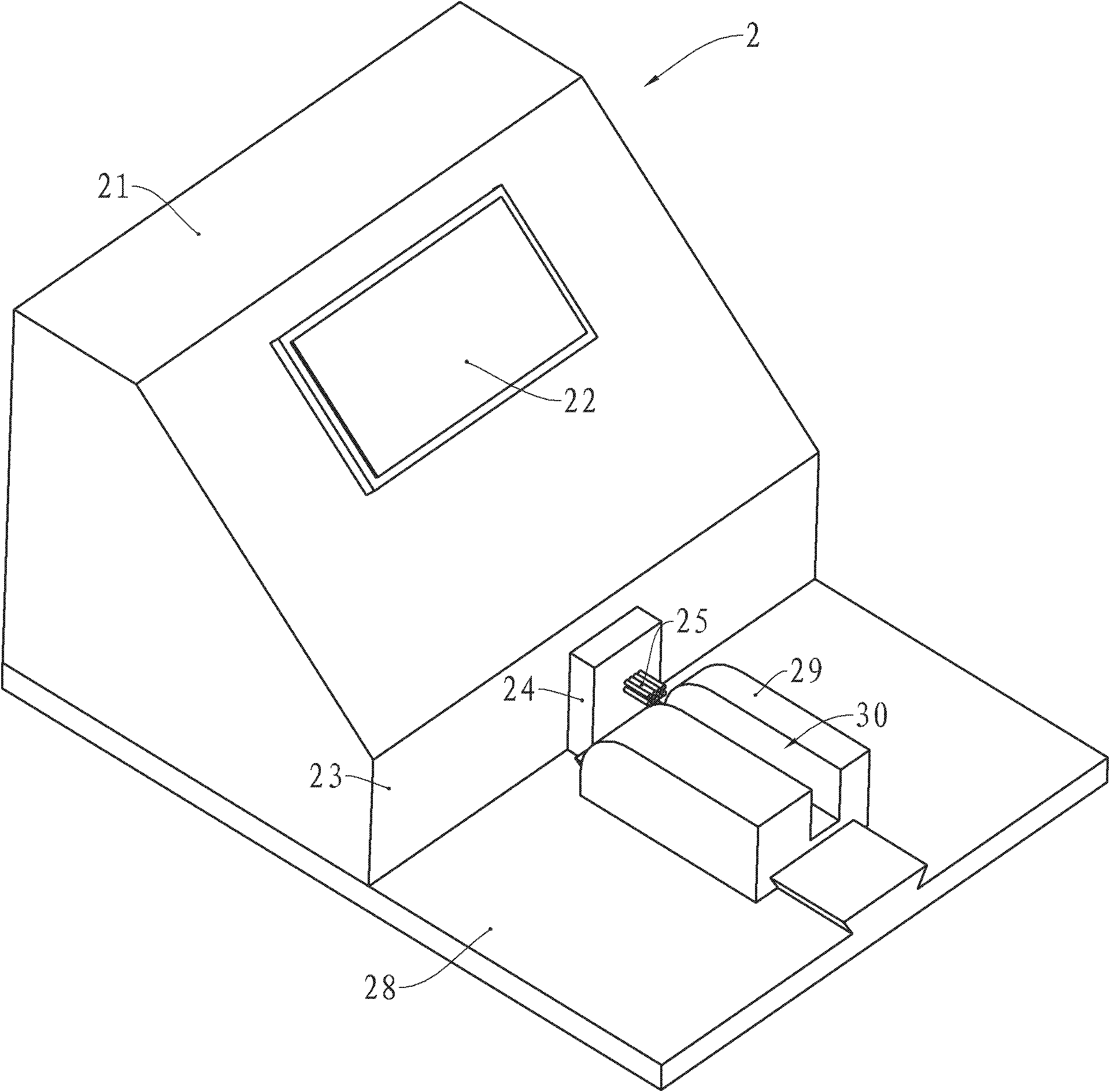
[0027] see figure 2 , The chip tester 2 provided by the present invention has a housing 21, and the housing 21 is provided with a display screen 22 as a test result display device. Of course, in practical application, multiple LED lamps can also be used as the detection result display device.

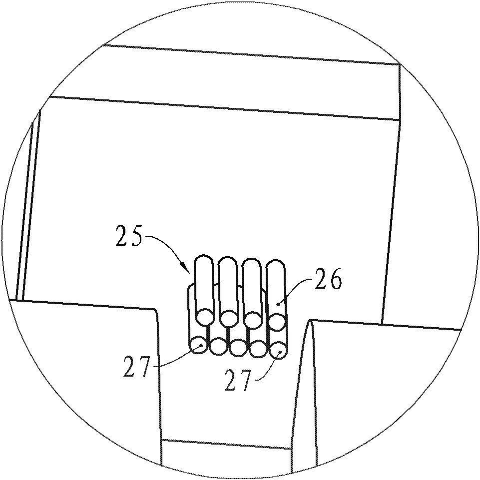
[0028] A side wall 23 of the housing 21 is provided with a protrusion 24 extending outward from the side wall 23, and the protrusion 24 is provided with nine detection pins 25 extending outward from the outer wall of the protrusion 24, as image 3 As shown, nine detection pins 25 are divided into two groups, one group is detection pins 26, including four detection pins located in the upper row and three detection pins located in the middle of the lower row, the first group of detection pins 26 and the first ink cartridge chip A set of electrical contact connections is used to detect the correctness of the data stored in the ink cartridge chip.

[0029] The second group of detection n...


PUM


Abstract

The invention provides a chip tester and a test method thereof. The tester comprises a case which is provided with a detection needle and a detection result display device, wherein the case is provided with a circuit board provided with a first detection unit, the first detection unit is provided with a microcontroller and a storage, the storage stores preset data, the circuit board is provided with a second detection unit which comprises a frequency comparer, and one output end of the second detection unit is connected with the detection needle. The method comprises the following steps: outputting a first detection signal and a second detection signal by the detection needle via the microcontroller; after receiving a first feedback signal and a second feedback signal, judging whether data represented by the first feedback signal is coincident with the preset data; meanwhile, inputting the second feedback signal to the frequency comparer; judging whether the input frequency is within the error range of frequency output by a frequency generator by the frequency comparer; and outputting the detection result. The invention can detect whether the piezoelectric sensor of an ink box can normally work nor not, and ensures that the ink box can be normally used.

Description

technical field [0001] The invention relates to a tester, in particular to a chip tester for testing ink cartridge chips and a test method for the chip tester. Background technique [0002] Inkjet printers are common printing devices that provide great convenience for modern offices. Existing inkjet printers mainly use ink cartridges detachably installed in the printing carriage to spray ink to paper to form required characters and patterns on paper. [0003] An existing ink cartridge such as figure 1 As shown, the ink cartridge 1 has a casing 11 , the casing 11 encloses a cavity containing ink, and an ink outlet 12 is provided below the cavity through which the ink in the cavity flows out. [0004] In order for the inkjet printer to display the current usage of the ink cartridge 1 , the ink cartridge 1 is mostly equipped with a chip that stores data related to the ink cartridge 1 . Such as figure 1 As shown, a chip 14 is provided on a side wall 13 of the housing 11 of t...

Claims


Application Information

Patent Timeline
Patent Type & Authority Applications(China)
IPC IPC(8): G01R31/28G01R31/00B41J2/175
Inventor 吴泽陈达飞黄先察徐长江
Owner ZHUHAI TIANWEI TECH DEV CO LTD
Why Eureka
Try Eureka