No bridge type power factor corrector with logical control

A technology of power factor correction and logic control, applied in the direction of output power conversion device, sustainable manufacturing/processing, high-efficiency power electronic conversion, etc., can solve problems such as diode conduction loss

Inactive Publication Date: 2010-11-17
GLACIALTECH +1
View PDF1 Cites 4 Cited by
  • Summary
  • Abstract
  • Description
  • Claims
  • Application Information

AI Technical Summary

Problems solved by technology

Unfortunately, however, the boost inductor discharges its stored energy through the body diode of the NMOSFET
This de-energized inductor current causes body diode conduction loss

Method used


Image

  • No bridge type power factor corrector with logical control
  • No bridge type power factor corrector with logical control
  • No bridge type power factor corrector with logical control

Examples


Embodiment Construction

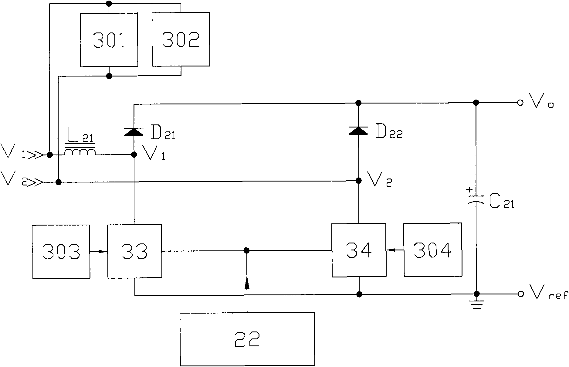
[0020] image 3 A block diagram showing a bridgeless power factor corrector with logic control according to the present invention, which includes a first input voltage terminal V i1 , a second input voltage terminal V i2 , a first connecting terminal V 1 , a second connection terminal V 2 , an output voltage terminal V o , a reference voltage terminal V ref , a boost inductor L21 , a filter capacitor C 21 , a first boost diode D 21 , a second boost diode D 22 , a first boost transistor assembly 33, a second boost transistor assembly 34, a high frequency switch controller 22, a first low frequency switch driver 303, a second low frequency switch driver 304, a first line voltage polarity The detector 301 and a second line voltage polarity detector 302 .

[0021] V i1 with V i2 Connect to an AC input voltage source; L 21 can be lumped / distributed over V i1 with V 1 Sometimes or / and V i2 with V 2 Room; C 21 placed in V o with V ref Between; D 21 with D 22 The a...


PUM


Abstract

The invention discloses a no bridge type power factor corrector with logical control, comprising a high frequency switch controller, a boosting inductor, a filter capacitor, two boosting transistor assemblies, two boosting diodes, two line voltage polarity detectors and two low frequency switch drivers. The two line voltage polarity detectors control the two low frequency switch drivers by signal coupling (optical coupling, magnetic coupling and the like), and the two line voltage polarity detectors and the high frequency switch controller drive the two boosting transistor assemblies by a control logic (or logic, nand logic and the like), so that the boosting inductor can release the stored energy by virtue of the channel of the two boosting transistor assemblies, intrinsic-barrier diode conduction loss can be reduced, and efficiency is improved.

Description

technical field [0001] The present invention relates to a bridgeless power factor corrector, especially a bridgeless power factor corrector with logic control, wherein the boost inductor releases its stored energy through the channel of the boost transistor component to reduce the body diode conduction pass losses and improve efficiency. Background technique [0002] In general, a resistor consumes real power because the line current is in phase with the line voltage (in phase with); an inductor or capacitor stores imaginary power because the line current and line voltage are ninety degrees out of phase (in phase with quadrature with). Resistive loads consume only real power rather than resistive loads that not only consume real power but also store imaginary power. Imaginary power increases unnecessary line currents and line losses. Therefore, the power company requires that the power factor (Power Factor, PF) of the large-scale electric equipment be corrected to an acce...

Claims


Application Information

Patent Timeline
Patent Type & Authority Applications(China)
IPC IPC(8): H02M1/42
CPCY02B70/126Y02B70/10Y02P80/10
Inventor 王志良余金生
Owner GLACIALTECH
Why Eureka
Try Eureka