Reflection-type optoelectronic switch and object detection method

A photoelectric switch, reflective technology, applied in electronic switches, electrical components, line-of-sight measurement, etc., can solve the problem of rising cost of BGS photoelectric switches

Inactive Publication Date: 2010-11-17
YAMATAKE HONEYWELL CO LTD
View PDF6 Cites 4 Cited by
  • Summary
  • Abstract
  • Description
  • Claims
  • Application Information

AI Technical Summary

Problems solved by technology

Then, in such a method, a memory and a computer are required, which leads to the problem that the cost of the BGS photoelectric switch increases

Method used


Image

  • Reflection-type optoelectronic switch and object detection method
  • Reflection-type optoelectronic switch and object detection method
  • Reflection-type optoelectronic switch and object detection method

Examples


no. 1 approach

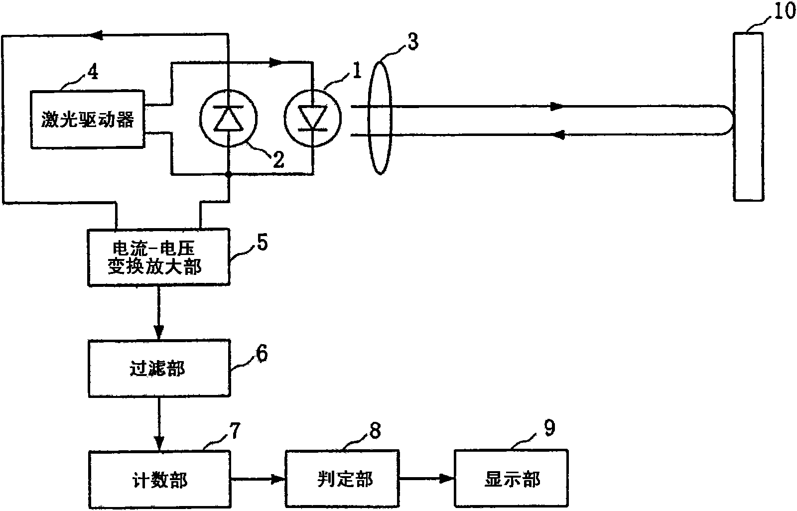
[0043] Hereinafter, embodiments of the present invention will be described with reference to the drawings. figure 1 is a block diagram showing the structure of the BGS photoelectric switch according to the first embodiment of the present invention.

[0044] figure 1 The BGS photoelectric switch has: a semiconductor laser 1 that emits laser light, a photodiode 2 that converts the light output of the semiconductor laser 1 into an electrical signal, collects and emits the light emitted by the semiconductor laser 1, and collects the returned light of the object 10 Light is incident on the lens 3 of the semiconductor laser 1, the laser driver 4 that drives the semiconductor laser 1, the current-voltage conversion amplifier 5 that converts the output current of the photodiode 2 into a voltage and amplifies it, and the output from the current-voltage conversion amplifier 5 The filter unit 6 that removes the carrier wave from the voltage, and the counting unit 7 that counts the num...

no. 2 approach

[0060] Next, a second embodiment of the present invention will be described. This embodiment is a more specific description of the counting unit 7 of the first embodiment. Figure 5 It is a block diagram showing the configuration of the counting unit of the BGS photoelectric switch according to the second embodiment of the present invention.

[0061] The counting unit 7 of the present embodiment has a rise detection unit 70 , a fall detection unit 71 , time measurement units 72 and 73 , and a comparison unit 74 .

[0062] Figure 6 It is a diagram for explaining the operation of the counting unit 7 of this embodiment, and is also a schematic diagram showing the waveform of the output voltage of the filter unit 6 , that is, the waveform of MHP. Figure 6 Among them, H1 is a threshold for detecting an increase in MHP, and H2 is a threshold for detecting a decrease in MHP.

[0063] The rise detection unit 70 detects the rise of MHP by comparing the output voltage of the filter u...

no. 3 approach

[0075] Next, a third embodiment of the present invention will be described. This embodiment is to describe the case where the reference half period Th / 2 is adopted in the BGS photoelectric switch of the first embodiment. Figure 8 It is a schematic diagram of the configuration of the counting unit of the BGS photoelectric switch according to the third embodiment of the present invention.

[0076] The counting unit 7 of the present embodiment has a rise detection unit 70 , a fall detection unit 71 , time measurement units 75 and 76 , and a comparison unit 77 .

[0077] Figure 9 It is a diagram for explaining the operation of the counting unit 7 of the present embodiment, and is also a schematic diagram showing the waveform of the output voltage of the filter unit 6 , that is, the waveform of MHP.

[0078] The operations of the rise detection unit 70 and the fall detection unit 71 are the same as those of the second embodiment.

[0079] The time measuring unit 75 measures th...


PUM


Abstract

The invention relates to a reflection-type optoelectronic switch which realizes favorable precision by simple and cheap structure by using a self-mixed type laser counter. The reflection-type optoelectronic switch comprises a semiconductor laser (1), a detection unit (an optoelectronic diode (2) and a current-voltage conversion amplifying part (5)) and a distance judgment processing unit (a filtering part (6), a counting part (7) and a judging part (8)), wherein the detection unit is used for detecting electric signals comprising interference waveform generated by self-mixed effect of laser emitted by the semiconductor laser (1) and light returned by an object (10); and the distance judgment processing unit is used for judging whether the object (10) is nearer or further than the preset reference distance according to the information of the interference waveform.

Description

technical field [0001] The invention relates to a reflective photoelectric switch, in particular to a reflective photoelectric switch and an object detection method for detecting whether the distance to an object is farther or shorter than a prescribed reference distance. Background technique [0002] In the past, as a kind of reflective photoelectric switch, it is known to measure whether the distance from the photoelectric switch to the object is far or short than the prescribed reference distance and set the reflective (Background Suppression, hereinafter referred to as BGS) photoelectric switch (for example, Refer to Patent Document 1, Patent Document 2). According to such a BGS photoelectric switch, only an object can be detected without detecting a background. [0003] On the other hand, as a distance meter that utilizes the interference of light emitted by a laser, a laser measuring instrument utilizing the interference (self-mixing effect) of the output light of the...

Claims


Application Information

Patent Timeline
Patent Type & Authority Applications(China)
IPC IPC(8): H03K17/94G01S17/48
Inventor 上野达也
Owner YAMATAKE HONEYWELL CO LTD
Why Eureka
Try Eureka