Plate shearing machine

A technology of shearing machine and frame, which is applied in the direction of shearing device, shearing machine equipment, metal processing equipment, etc., and can solve the problems of failure to meet the use requirements, low control accuracy, and cutting off the intermediate material, etc.

Inactive Publication Date: 2010-11-24
中船海洋与防务装备股份有限公司
View PDF6 Cites 10 Cited by
  • Summary
  • Abstract
  • Description
  • Claims
  • Application Information

AI Technical Summary

Problems solved by technology

[0004] However, the plate shearing machine used in the above method needs to cut the middle of the sheet material. If the shearing stroke is too small, the remaining material in the middle cannot be cut off, and if the shearing stroke is too large, the arc parts on both sides will be damaged. Therefore, it requires that the shear stroke can be precisely controlled
However, the shearing stroke of the current existing shearing machine is controlled by the oil cylinder and the travel switch, and the control accuracy is not high. Usually, it can only shear the entire sheet or one end of the sheet, which cannot meet the requirements of use.

Method used


Image

  • Plate shearing machine
  • Plate shearing machine
  • Plate shearing machine

Examples


Embodiment Construction

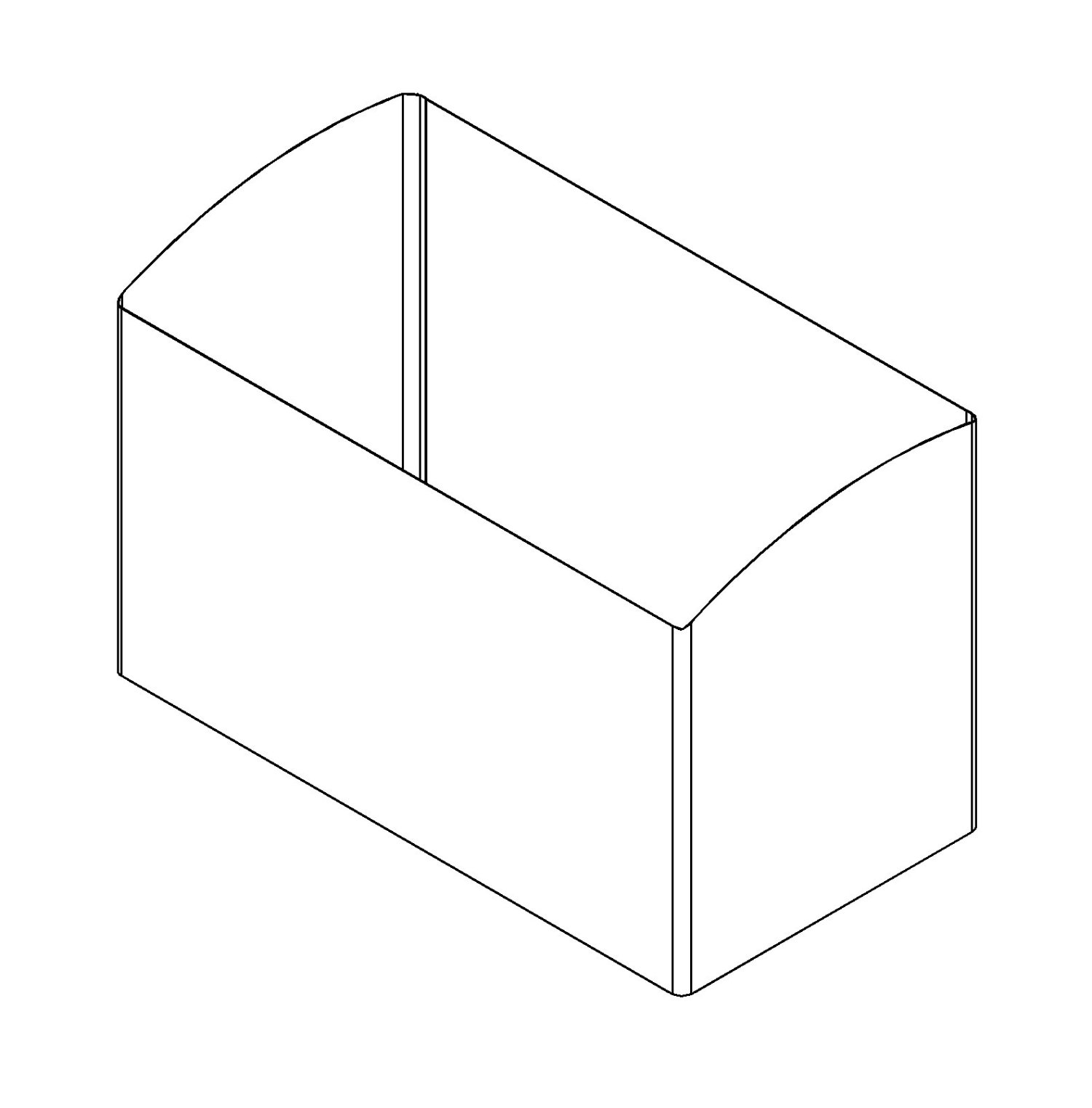
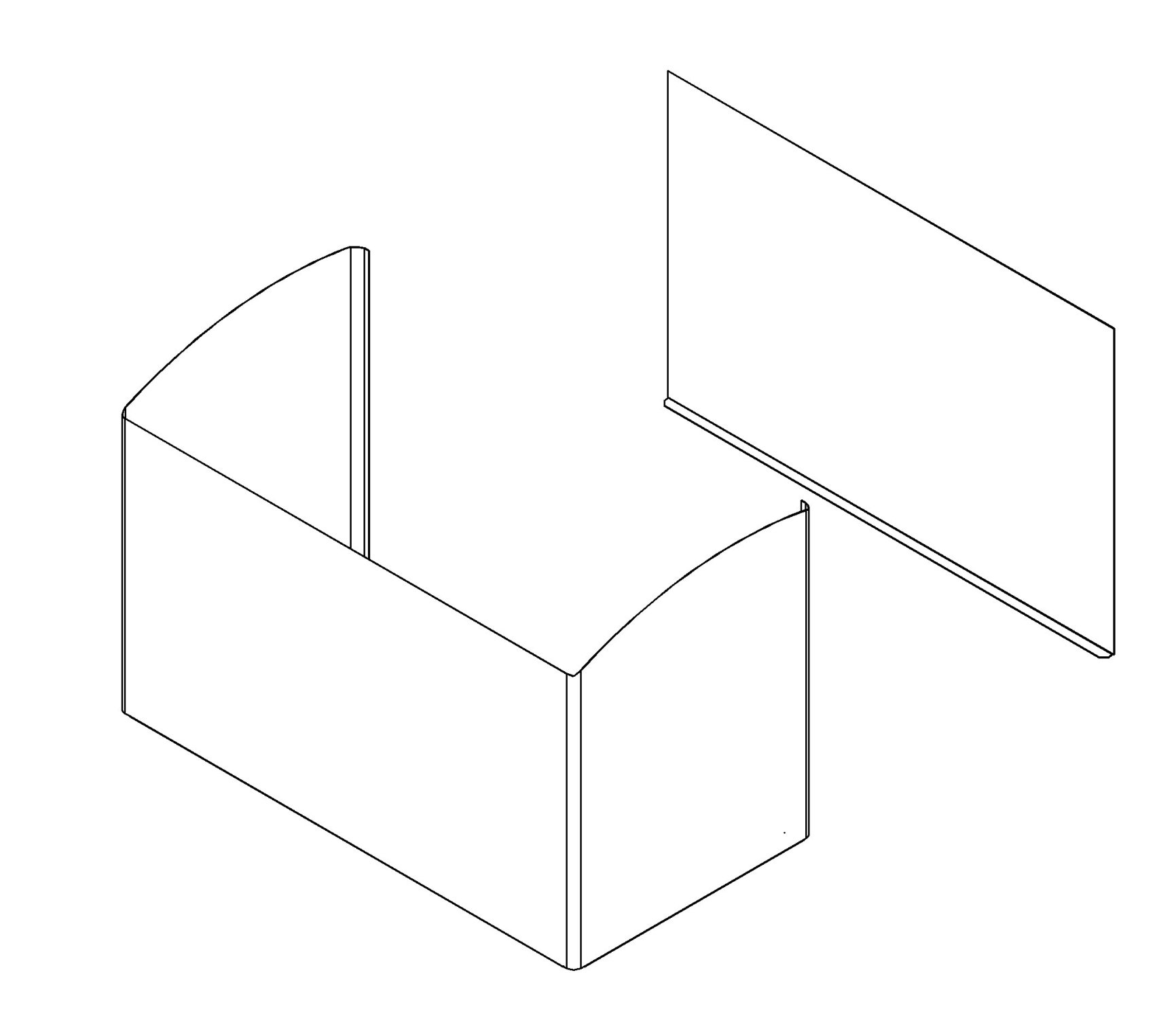
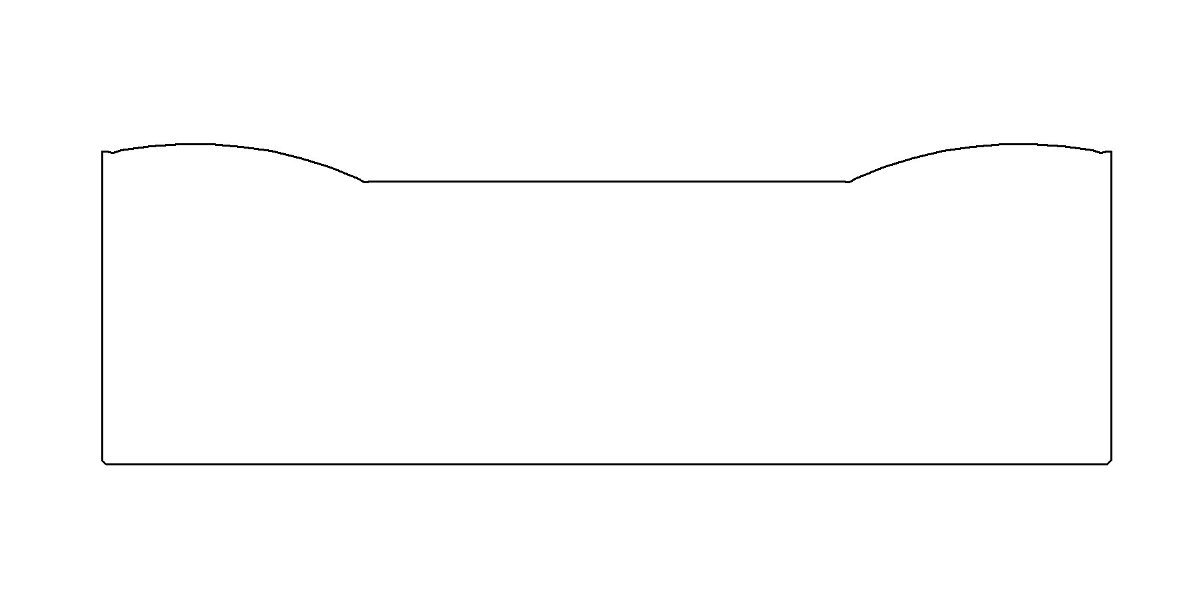
[0017] A shearing machine, such as Figure 4 , Figure 5 , Figure 6 , Figure 7 , including a frame 1 and a slider 2 installed on the frame 1 through a linear guide rail pair 14, a lower scissor 3 is fixed on the frame, an inclined upper scissor 4 is fixed on the slider, and the upper scissors and the lower scissors are staggered from each other, The blade surfaces are flush with each other; multiple (two, three or more) nuts 5 are fixed on the top of the slider, and each nut is equipped with a longitudinal screw 6, and the top of the screw can change the transmission The bevel gear steering boxes 7 in the direction, each bevel gear steering boxes are connected by joint shafts 15, and one of the bevel gear steering boxes is connected with the servo motor 8. The bevel gear steering box can transform the rotation in the horizontal direction into the rotation in the vertical direction. It is an existing technology, and it can be only two bevel gears meshing with each other at...


PUM


Abstract

The invention discloses a plate shearing machine. The plate shearing machine comprises a machine frame and a sliding block which is arranged on the machine frame through a linear guide track pair, wherein a lower shear and an upper shear are fixed on the machine frame and the sliding block respectively; nuts and screw rods are arranged above the sliding block; the top parts of the screw rods are provided with bevel gear steering boxes; and the bevel gear sheering boxes are connected with one another through coupling shafts and are driven by a same servo motor. The servo motor can synchronously drive each bevel gear steering box to rotate through the coupling shafts, and the bevel gear steering boxes drive each screw rod to rotate synchronously to ensure that the whole sliding block can move up and down synchronously. The sliding block carries the upper shear to move to realize the shearing of a workpiece. Because the rotational angle of the servo motor can be accurately controlled, the rotational angle of the screw rods can be accurately controlled, and the distance for the sliding block to move up and down can be accurately controlled. By controlling the distance for the sliding block to move up and down, the shearing stroke of the plate shearing machine is controlled. Therefore, the shearing stroke of the plate shearing machine can be accurately controlled, and the middle part of a plate can be sheared.

Description

technical field [0001] The invention relates to mechanical equipment for cutting sheet metal parts, in particular to a shearing machine. Background technique [0002] The refrigerators used in supermarkets and stores to display ice cream and chilled goods waiting for sale are usually horizontal refrigerators. The metal shell of the horizontal refrigerator is composed of a flat back panel and a C-shaped hoard made of bent metal sheets, such as figure 1 , figure 2 . In order to facilitate customers to watch the goods in the cabinet, the top surface of the horizontal freezer is usually designed to be arc-shaped, the middle of the top surface of the C-shaped enclosure is a straight line, and the two sides are upward arcs; used to bend the C-shaped enclosure The workpiece (metal sheet) needs to be a structure with convex arcs on the left and right sides and a straight line concave in the middle, such as image 3 . At present, the metal sheet of this structure is usually form...

Claims


Application Information

Patent Timeline
Patent Type & Authority Applications(China)
IPC IPC(8): B23D15/08B23D15/12
Inventor 陈尚贵赵刚盛少琴施理军黄琼闫振刘力辛海斌
Owner 中船海洋与防务装备股份有限公司
Why Eureka
Try Eureka