Reducer capable of regulating return difference

A reducer and adjustable technology, applied in the direction of mechanical equipment, transmission parts, gear transmissions, etc., can solve the problems of increased operating costs, increased processing costs, frequent accidents, etc. Effect of service life and reduction of manufacturing cost

Inactive Publication Date: 2012-05-23
张爱华
View PDF0 Cites 1 Cited by
  • Summary
  • Abstract
  • Description
  • Claims
  • Application Information

AI Technical Summary

Problems solved by technology

[0005] At present, the only way to reduce the backlash in the machinery manufacturing industry is to improve the machining accuracy, use precision machine tools and special processes to greatly improve the gear accuracy, and reduce the backlash of the teeth to the smallest possible level, which is very difficult to process , which not only greatly increases the processing cost, but also often fails to meet the requirements for use
Especially after a period of operation of the reducer, it will inevitably wear and tear, which will increase the backlash of the teeth, thereby increasing the hysteresis, reducing the accuracy of the equipment, and even making the equipment unusable.
Since the reducer is worn out, according to the current state of technology, it cannot be repaired. The only way is to replace the reducer with a new one. This not only increases the operating cost, but also often causes unacceptable accidents to occur frequently
There is currently no viable solution to this problem

Method used


Image

  • Reducer capable of regulating return difference
  • Reducer capable of regulating return difference
  • Reducer capable of regulating return difference

Examples


no. 2 Embodiment

[0084] The second embodiment of the present invention can realize automatic adjustment of hysteresis.

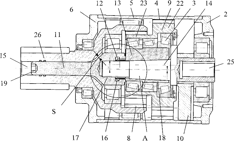
[0085] Figure 7 It is a structural sectional view of the second embodiment of the speed reducer with adjustable hysteresis of the present invention.

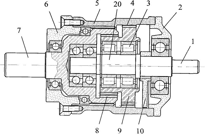
[0086] Such as Figure 7 As shown, the speed reducer with adjustable hysteresis of the present invention includes: a housing 5, a double planetary gear 9 mounted on the eccentric journal 42 of the input shaft through a bearing, an input shaft 41 with one end mounted on the input end cover 2, a mounting On the output shaft 39 on the output end cover 6, the input shaft remains at the center of the speed reducer, the first gear 22 of the double planetary gear meshes with the fixed ring gear 4 on the housing, and the second gear 23 of the double planetary gear Mesh with the gear 8 of the output shaft, the input shaft and the output shaft are in a straight line, and a balance weight 10 is also installed on the input shaft.

[0...


PUM


Abstract

The invention relates to a reducer capable of regulating return difference. The reducer comprises an outer shell, a compound planet gear, an input shaft and output shaft, wherein a first gear I of the compound planet gear is meshed with the fixed gear ring of the outer shell, and a second gear II thereof is meshed with the gear of the output shaft; the input shaft and the output shaft are in the same straight line, the eccentric shaft neck of the input shaft is provided with taper, and an eccentric sleeve is arranged between the eccentric shaft neck of the input shaft and the bearing of the compound planet gear; the eccentric sleeve is provided with a tapered hole, and the front end of the eccentric sleeve is provided with an elastic hanger; the eccentric shaft neck of the input shaft is tightly matched with the tapered hole of the eccentric sleeve; the centre hole of the output shaft is internally provided with an adjusting screw rod, a screwed hole at the large end of the adjusting screw rod is connected with an external thread at the other end of the input shaft; and the elastic hanger of the eccentric sleeve is inserted into a hanger groove at the larger end of the adjusting screw rod, and the larger end of the adjusting screw rod is connected with the output shaft through a bearing. The invention can carry out adjustment to enable the gear return difference to restore to an expected value, has simple, convenient and feasible adjustment, reduced gear manufacturing cost and prolonged service life. The second embodiment of the invention can realize automatically regulating return difference.

Description

technical field [0001] The invention belongs to the field of speed reducers, and in particular relates to a speed reducer with adjustable hysteresis that can be adjusted to restore the gear hysteresis to an expected value, reduce gear manufacturing costs and prolong service life. Background technique [0002] Because the general gear reducer has the necessary tooth side clearance, when the reducer rotates in the opposite direction, it must first idling until the other side of the tooth side contacts, so as to drive the output shaft to rotate in the opposite direction. This idling distance is the backlash. Difference. In some occasions that require precise transmission, such as precision machine tool feed reducer, robot joint reducer, solar tracking reducer, reducer for some automatic systems, and other reducers that require precise positioning, etc., it is necessary to reduce the hysteresis Reduced to as small as possible, otherwise it will not work properly. The reducer u...

Claims


Application Information

Patent Timeline
Patent Type & Authority Patents(China)
IPC IPC(8): F16H1/32F16H1/36F16H57/08
CPCF16H1/32
Inventor 杨天博
Owner 张爱华
Why Eureka
Try Eureka