Fixture whole lamp aging detection line and operating mode thereof

A working method and detection line technology, applied in the field of aging detection of lighting lamps, can solve the problems of large assembly line structure, easy to cause danger, low aging efficiency, etc., and achieve improved aging efficiency, less floor space, and compact and reasonable equipment structure Effect

Inactive Publication Date: 2010-11-24
胡三传
View PDF5 Cites 21 Cited by
  • Summary
  • Abstract
  • Description
  • Claims
  • Application Information

AI Technical Summary

Problems solved by technology

The assembly line structure basically realizes the semi-automatic aging and detection of the bracket lamp. However, on the assembly line, the bracket lamp is placed horizontally, and the horizontal position of each row on the assembly line can only hold one bracket lamp. The number of bracket lamps clamped by the assembly line is limited, which not only makes the overall structure of the assembly line huge, but also the number of aging bracket lamps is limited by the volume of the assembly line, and the aging efficiency is low; The power connection of the lamp is still done manually. The operator needs to connect the instantaneous high-voltage electricity to the whole lamp after the aging bracket to conduct a withstand voltage test, and then connect the power test source to conduct a power test for final screening. This kind of operation steps is not only a waste of manpower, but also inefficient, and not safe enough, especially the withstand voltage test connected to high voltage, which is very easy to cause danger when the operator manually operates

Method used


Image

  • Fixture whole lamp aging detection line and operating mode thereof
  • Fixture whole lamp aging detection line and operating mode thereof
  • Fixture whole lamp aging detection line and operating mode thereof

Examples


Embodiment Construction

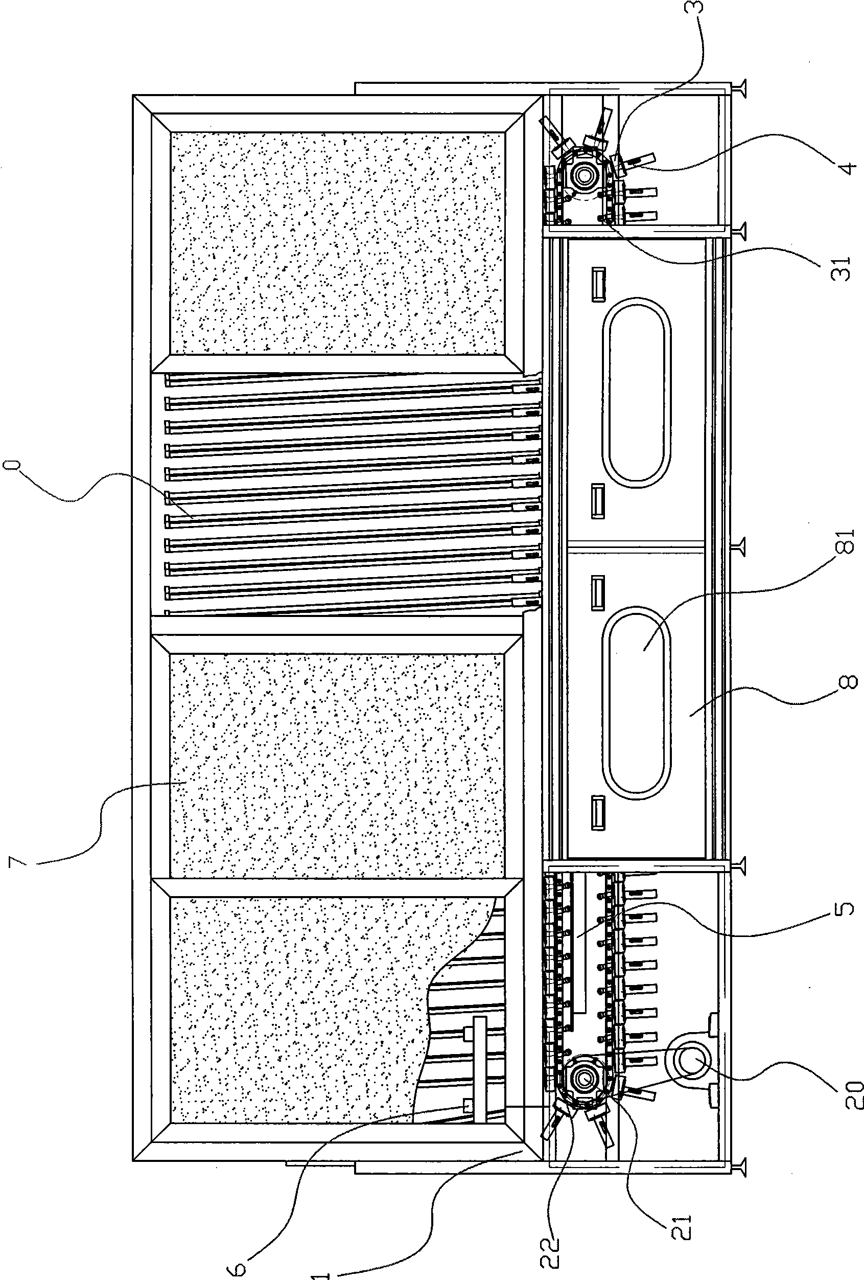
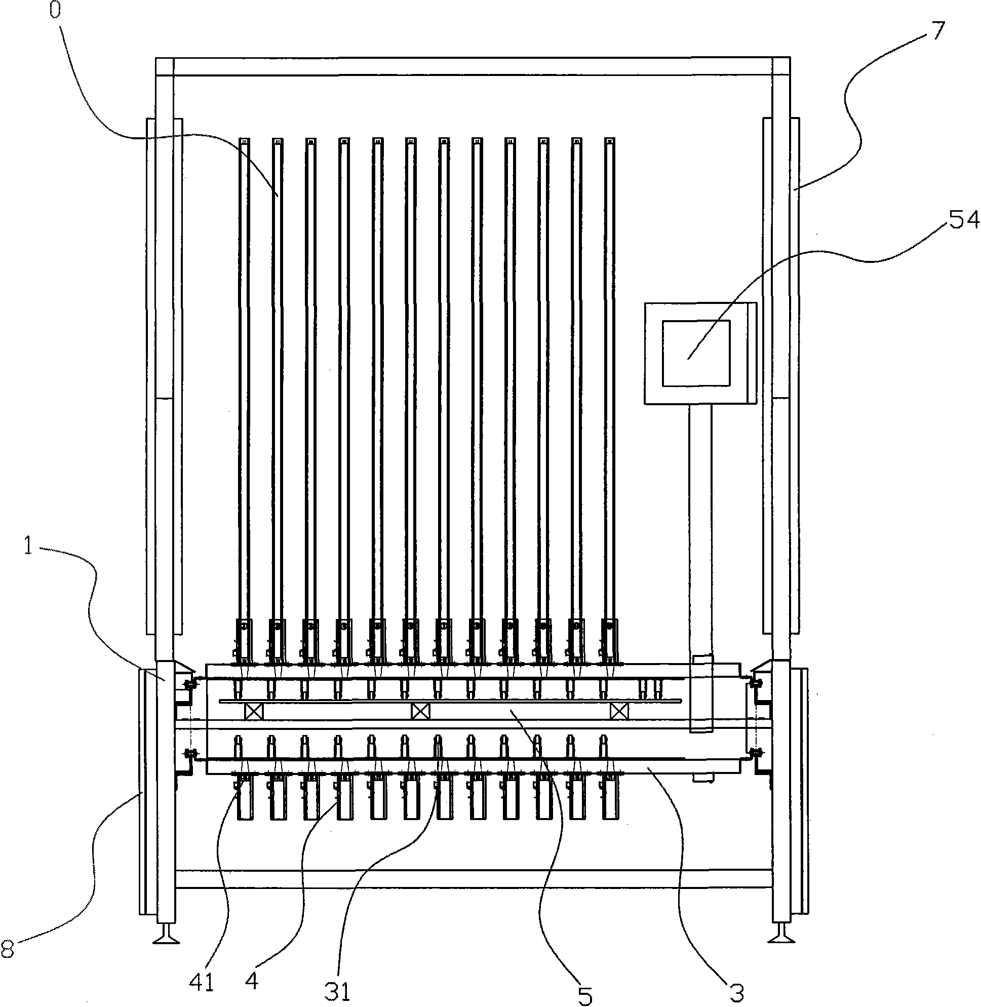
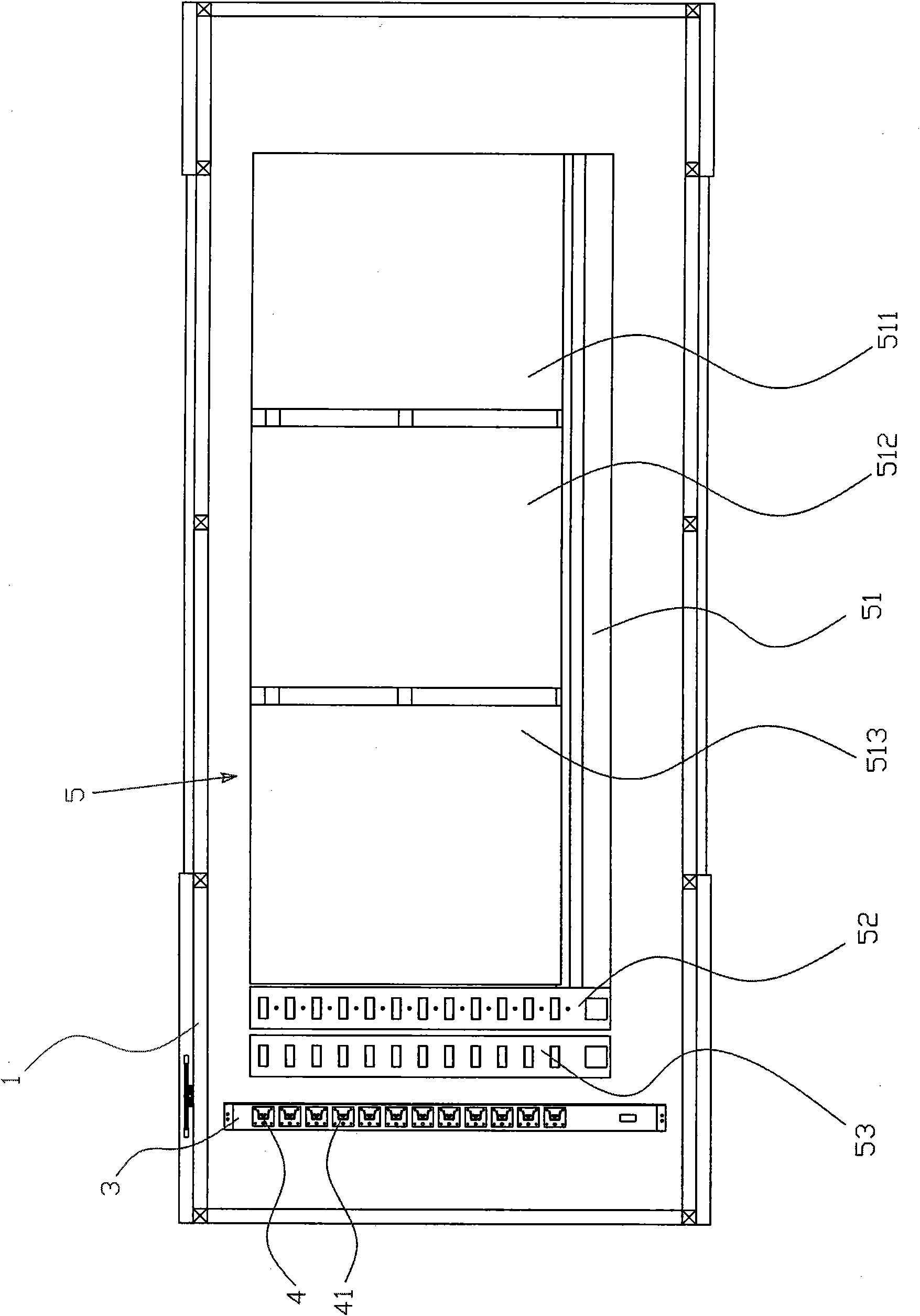
[0025] refer to Figure 1 ~ Figure 2 , the bracket whole lamp aging detection line provided by the present invention includes a frame 1 and a power mechanism 20. A conveying chain 22 is installed on the frame 1 through a transmission assembly 21, and the transmission assembly 21 is connected to the power mechanism 20 by transmission. The assembly 21 includes a transmission sprocket, and the driving and driven wheels balancedly distributed on the frame 1. During operation, the power mechanism 20 transmits to the transmission assembly 21 through the chain, and then drives the movement of the conveying chain 22 from front to back, and obtains a basic In the present invention, the conveying chain 22 is equipped with chain plates 3, and the chain plates 3 are arranged and installed above the conveying chain 22 in order, as the assembly of the fixed bracket whole lamp 0, wherein each chain plate 3 top is along its There are several bracket lamp clamping seats 4 arranged in a row in ...


PUM


Abstract

The invention discloses a fixture whole lamp aging detection line, which comprises a fixture and a power mechanism, wherein the machine frame is provided with conveying chains through a transmission assembly; the transmission assembly is in transmission connection with the power mechanism; chain plates are arranged above the conveying chains in a row; a plurality of fixture lamp holders are arranged above the chain plates in a row along the length direction of the chain plates; conductive sockets for fixture whole lamps to be inserted into are arranged in the fixture lamp holders; conductive brushes which are connected with the conductive sockets of the fixture lamp holders electrically are arranged below the chain plates respectively; the machine frame is also provided with a conductive plate connected with an external aging power supply; the conductive plate is positioned below the upper-layer conveying chains; conductive areas corresponding to the middle and rear parts of the conveying chains are distributed on the upper surface of the conductive plate; and the conductive areas are contacted correspondingly through the conductive brushes above the conductive area. The fixture whole lamp aging detection line can be used for mounting a plurality of fixture whole lamps, makes equipment structure compact and reasonable, ensures high aging efficiency and is a fixture whole lamp aging detection line with high comprehensive performance.

Description

technical field [0001] The invention relates to an aging detection technology of an illuminating lamp, in particular to an aging detection line for a bracket whole lamp (T4, T5 bracket lamp) and a working method thereof. Background technique [0002] In the production process of lamps and lanterns, in order to ensure the quality of products, it is necessary to carry out aging and online detection of components. The main method of aging is to make the lamps last for a certain period of time in abnormal working environments, such as environments exceeding or below the rated voltage. Luminous work, in this process, lamps with unqualified components will be damaged, so that defective products can be screened out; while online inspection is to apply high-voltage impact to the lamps for withstand voltage testing, and the power of the lamps During the test, the components of defective products will also be washed out when the high voltage is connected, or they will be screened out ...

Claims


Application Information

Patent Timeline
Patent Type & Authority Applications(China)
IPC IPC(8): G01R31/44
Inventor 胡三传
Owner 胡三传
Why Eureka
Try Eureka