Target clustering method of imaging satellite observation scheduling

A technology of target clustering and imaging satellites, which is applied in the field of aerospace applications, can solve problems such as insignificant effects, low observation efficiency, and poor operability, and achieve the effects of saving calculation time, narrowing the search range, and avoiding repeated calculations

Inactive Publication Date: 2010-11-24
NAT UNIV OF DEFENSE TECH
View PDF2 Cites 41 Cited by
  • Summary
  • Abstract
  • Description
  • Claims
  • Application Information

AI Technical Summary

Problems solved by technology

[0004] 1. The satellite can only image from one observation angle at the same time;
[0005] 2. Satellite observation tasks must be performed within the visible time window with the observation target;
[0007] 4. Satellite observation must meet the operational constraints of the satellite itself
[0017] In summary, it can be found that in the current research on imaging satellite scheduling problems, these literatures only give some simple clustering rules, which are not very operable, or the effect is not obvious
In fact, for imaging satellites with a str

Method used


Image

  • Target clustering method of imaging satellite observation scheduling
  • Target clustering method of imaging satellite observation scheduling
  • Target clustering method of imaging satellite observation scheduling

Examples


Embodiment 1

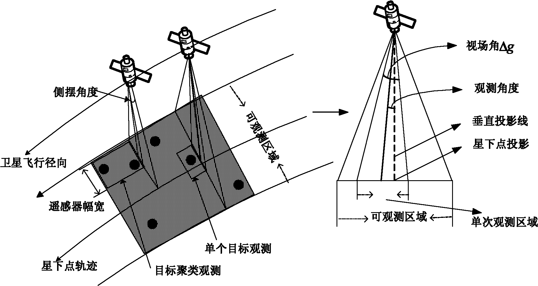
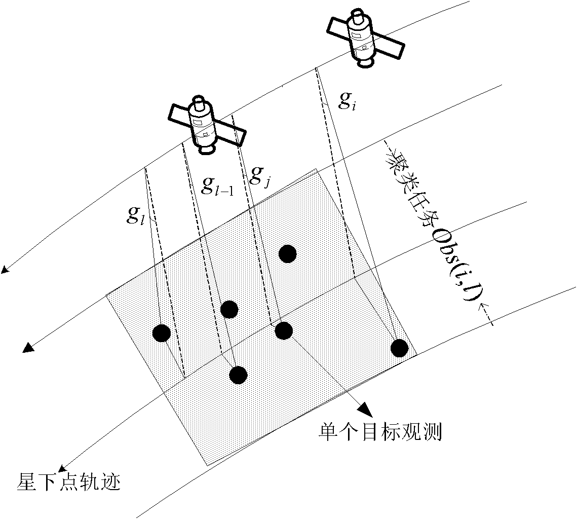
[0058] Embodiment 1: as figure 1 , figure 2 and image 3 As shown, according to the satellite imaging mechanism, it can be seen that the satellite’s spaceborne remote sensor (camera) can cover a horizontal observation strip on the ground at one time. The width of the strip is the width of the satellite’s field of view, which is defined by the In the radial direction, the length of the observation swath is determined by the radial flight distance of the satellite during the duration of the observation activity. The observable area of ​​the satellite is usually a symmetrical area with the sub-satellite point track line as the center line. The boundary width of the symmetrical area is determined by the maximum roll angle of the satellite, and the single observation area of ​​the satellite is determined by the satellite's on-board It is determined by the field of view of the remote sensor. The roll angle used by the satellite to observe the target is defined as the observation...

Embodiment 2

[0169]Embodiment 2: The principle and steps of the target clustering method for imaging satellite observation scheduling in this embodiment are basically the same as those in Embodiment 1. The only difference is that this embodiment omits the calculation of the best observation angle for observation activities.

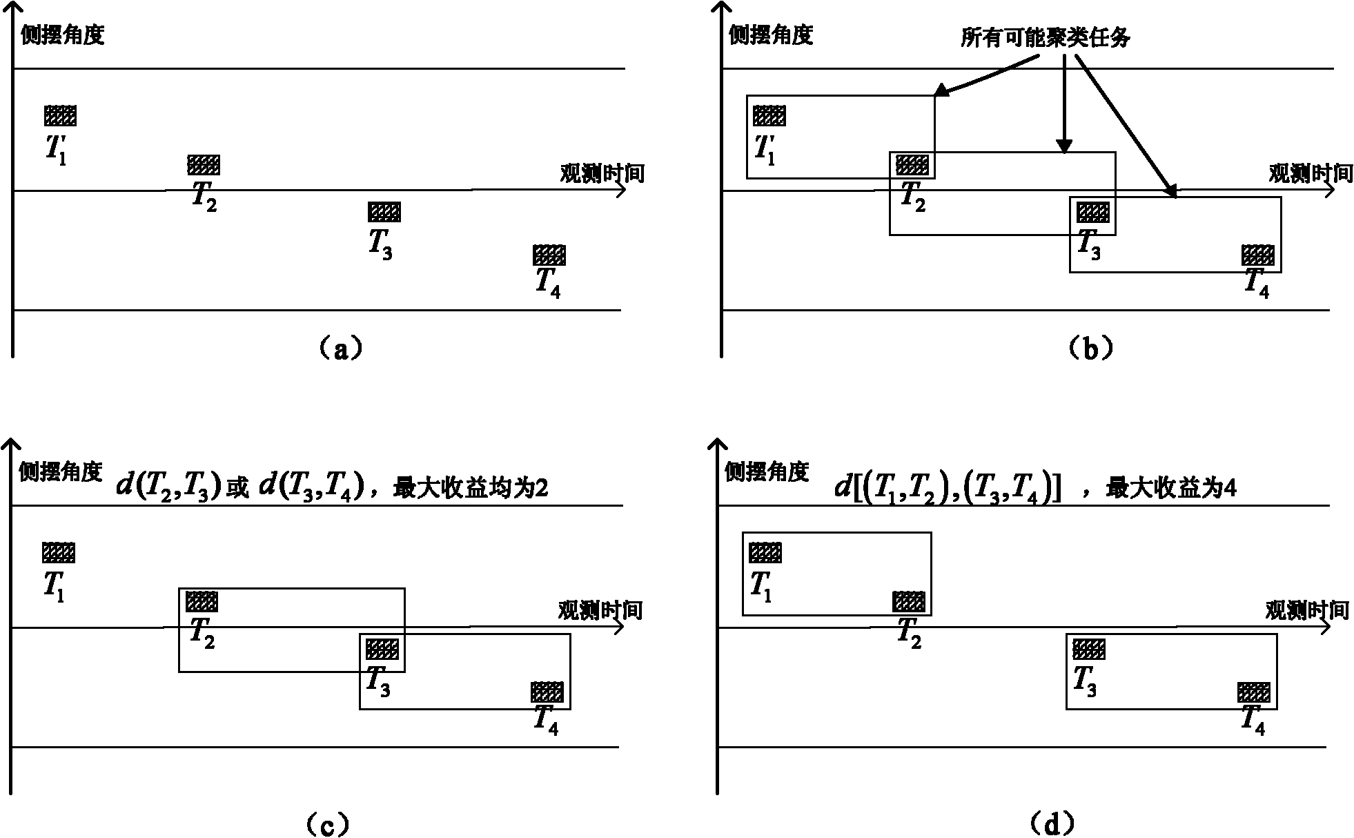
[0170] Such as Figure 7 As shown, it is assumed that the maximum number of side swings in a single orbit of a satellite is 2 times, and there are 4 observation targets in total, that is, the satellite needs to cover the maximum number of targets within 2 side swing observation opportunities. Figure 7 (b) is a schematic diagram of all possible task clustering methods between tasks. In order to obtain the maximum coverage scheme, a dynamic programming method is used to solve the maximum coverage model as in Example 1.

[0171] let f k (T i ) for T i is the maximum income of the k-th clustering task of the starting task node, d(T i ,T l ) are the start and end tas...


PUM


Abstract

The invention discloses a target clustering method of imaging satellite observation scheduling. In the method, an optimal target clustering scheme is obtained by obtaining target clustering conditions and qualities of satellite observation, a maximum gain value of the target clustering scheme of a satellite in the orbit circle and an optimal target clustering scheme and finishing a target clustering step, and a set of targets covered by various observation activities of the satellite is further obtained. The target clustering method of the imaging satellite observation scheduling can satisfy using rules and performance characteristics of various operations of the satellite with small computation cost, ensure that the satellite can finish more observation tasks within the given time and improve the using efficiency and the benefits of satellite resources, and has small imaging distortion.

Description

technical field [0001] The present invention mainly relates to the field of aerospace application technology, in particular to a method for scheduling, combining and optimizing imaging satellite observation tasks. Background technique [0002] Imaging satellites have unique advantages such as wide coverage, long operation time, no national boundaries and airspace restrictions, and no need to consider personnel safety. Therefore, since the appearance of imaging satellites, they have been highly valued by countries all over the world. Environmental protection, urban planning, and many fields such as agriculture and meteorology have played an important role. [0003] Usually, imaging satellites implement observations according to a predetermined observation plan, which specifies at what time, what observation angle, and which ground areas the satellite will image within a given time range. The observation plan is formulated by the satellite management department according to t...

Claims


Application Information

Patent Timeline
IPC IPC(8): G06T7/00
Inventor 贺仁杰姚锋邢立宁张正强
Owner NAT UNIV OF DEFENSE TECH
Why Eureka
Try Eureka