
Patsnap Eureka
For R&D, Patsnap Eureka makes reading and utilizing patents & technical documents easy.
Patsnap Eureka AIR
Designed for self-driven R&D workflows. Generate viable solutions, solve complex R&D challenges, empower your innovation with AI.

Patsnap Eureka Materials
Designed for material experts only. Revolutionize your material R&D, from search, analyze, to developing new materials.

TechResearch
Generate reliable direction feasibility study reports for your R&D in just a few steps.

TechSeek
Discover and master advanced knowledge NOW. Basics, ideas, possibilities, all at once.

TechMind
As an expert in R&D Theories, TechMind can generates customized viable solutions instantly.

TechRisk
Analyze your overall solution with one click, know your potential R&D risks in advance.

TechMonitor
Get weekly tech updates, stay abreast of the latest tech innovations and key insights.
Motor and rotor for dynamo-electric machine
A technology for rotating electric machines and electric motors, which is applied in the field of electric motors and can solve the problems of reduced magnetic flux, reduced motor torque, and complex stator structure
- Summary
- Abstract
- Description
- Claims
- Application Information
AI Technical Summary
Problems solved by technology
Method used
Image

Examples
no. 1 approach
[0111] First, based on Figure 1 to Figure 15 The first embodiment of the present invention will be described.
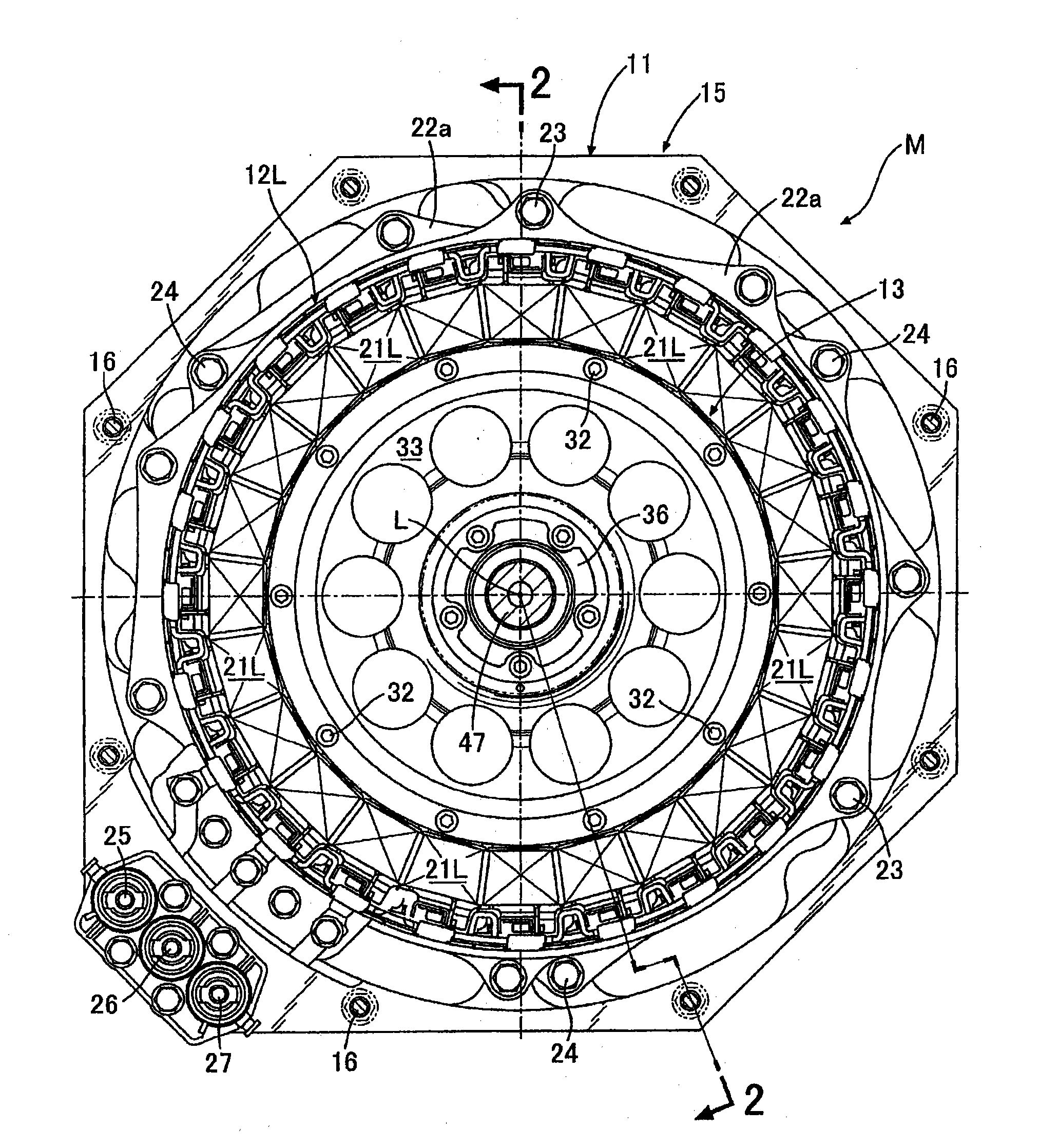
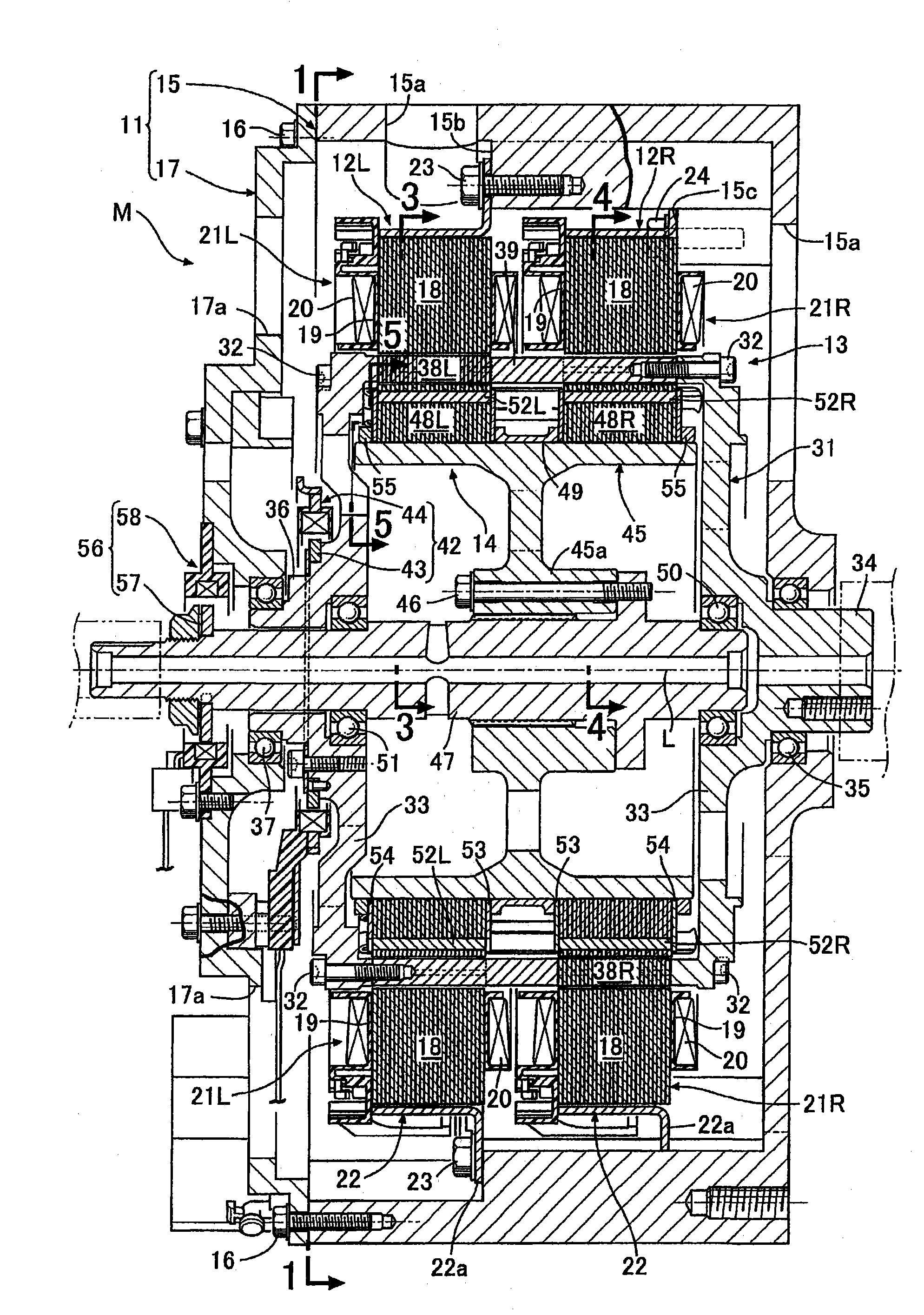
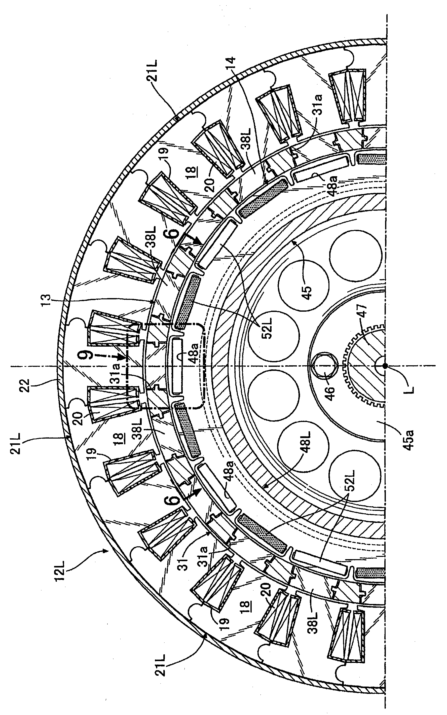
[0112] Such as Figure 7 As shown, the motor M of this embodiment includes: a housing 11, which is in the shape of an octagonal cylinder short in the direction of the axis L; and a ring-shaped first stator 12L and a second stator 12R, which are fixed to the housing. 11; a cylindrical outer rotor 13, which is housed inside the first and second stators 12L, 12R and rotates around the axis L; and a cylindrical inner rotor 14, which is housed in the outer rotor 13 internally and rotates about the axis L. The outer rotor 13 and the inner rotor 14 can rotate relative to the fixed first and second stators 12L and 12R, and the outer rotor 13 and the inner rotor 14 can rotate relative to each other.
[0113] by such as figure 1 as well as figure 2 It can be seen that the housing 11 is composed of a bottomed octagonal cylindrical main body 15 and an octagonal plate-sha...
no. 2 approach
[0159] Second, based on Figure 16 A second embodiment of the present invention will be described.
[0160] In the motor M of the first embodiment, the polarity of the first armature 21L... of the first stator 12A and the polarity of the second armature 21R... of the second stator 12B are adjacent to each other in the axis L direction. consistent. The second embodiment is an embodiment in which the first and second armatures 21L, 21R, .
[0161] Thus, by integrating the first armature 21L... and the second armature 21R... of the first embodiment as the armature 21..., the first stator 12A and the second stator 12B can be integrated into one stator 12. Accordingly, reduction in the number of components and further simplification of the structure can be achieved, and the motor M can function the same as that of the first embodiment.
no. 3 approach
[0163] Second, based on Figure 17 A third embodiment of the present invention will be described.
[0164] The third embodiment is an embodiment in which each of the first permanent magnet 52L or the second permanent magnet 52R constituting one magnetic pole of the inner rotor 14 is divided into two. In this case, in order to form one magnetic pole with two permanent magnets, it is necessary that the polarities of these two permanent magnets match.
PUM
 Abstract
Description
Claims
Application Information
 - R&D Engineer
- R&D Manager
- IP Professional
- Industry Leading Data Capabilities
- Powerful AI technology
- Patent DNA Extraction
Browse by: Latest US Patents, China's latest patents, Technical Efficacy Thesaurus, Application Domain, Technology Topic, Popular Technical Reports.
© 2024 PatSnap. All rights reserved.Legal|Privacy policy|Modern Slavery Act Transparency Statement|Sitemap|About US| Contact US: help@patsnap.com